
We are working on external RTC MCP7940(i2c) interfaced with nrf52840. Please check if drivers of the same for nrf52/51 are available or any implementation of CLOCK using MCP7940 with NRF?
Regards
Vishal Aditya
Embedded Software Engineer
We are working on external RTC MCP7940(i2c) interfaced with nrf52840. Please check if drivers of the same for nrf52/51 are available or any implementation of CLOCK using MCP7940 with NRF?
Regards
Vishal Aditya
Embedded Software Engineer
HI Vishal,
I am afraid that we do not have any dedicated drivers from the MCP7940. I am also not aware of any customers that have used the MCP7940 as the 32kHz clock source for the nRF5x series, but Ithink it should be possible.
We have TWI hardware drivers in our nRF5 SDK for the nRF51 and 52 series, see Driver support matrix.
Best regards
Bjørn

bjorn-spockeli
I am writing drivers by myself & stuck in the first step of I2C DETECT not happening.
SDK: nRF5_SDK_15.2.0_9412b96\examples\peripheral\twi_scanner
MCP7940 Break-out: https://rheingoldheavy.com/product/breakout-board-mcp7940/ which works perfectly with Arduino at I2C Address: 0x6F
But I2C DETECT not working with nrf52840 DK. Please suggest how to debug this issue? We have an Oscilloscope!
The connections are correct!
#define SCL NRF_GPIO_PIN_MAP(0,14)
#define SDA NRF_GPIO_PIN_MAP(0,13)
Connected to the same as per code via jumper wires. Please suggest any other possible way of debugging this issue. As MCP7940 works with Arduino(i2c scanner)
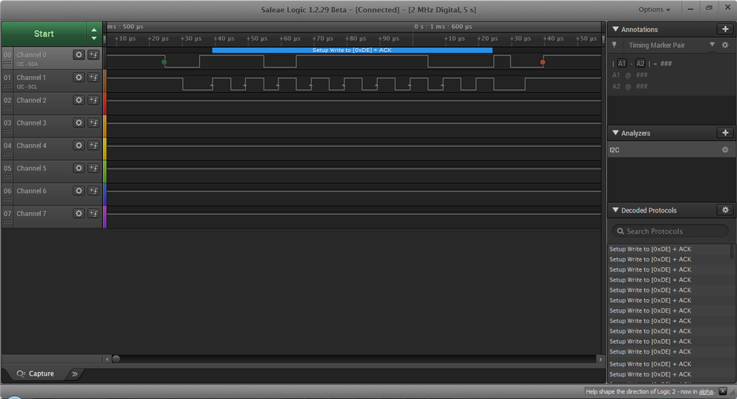
Please check the traces of the custom board nrf52840 & MCP7940(i2c) with the same code. 
Pull-ups: 4.7kohm in custom board
but in MCP7940 break-out board, it's 10kohm
#define SCL		           				 NRF_GPIO_PIN_MAP(0,14)
#define SDA		           				 NRF_GPIO_PIN_MAP(0,13)

//    for (address = 1; address <= TWI_ADDRESSES; address++)
//    {
				while(1)
				{
        err_code = nrf_drv_twi_rx(&m_twi, 0x6F, &sample_data, sizeof(sample_data));
        if (err_code == NRF_SUCCESS)
        {
            detected_device = true;
            NRF_LOG_INFO("TWI device detected at address 0x%x.\r\n", address);

        }
        NRF_LOG_FLUSH();
			}
Mr. bjorn,
Kindly respond to the codes posted and suggest solutions.

The traces still show that the slave, i.e. MCP7940 is not ACKing the read. Can you enable the analog sampling in addition to the digital sampling of the salea? That way we can see if the MCP7940 is attempting to pull eh the SDA line high or not. Also how large is sample_data?
What does the trace from the Arduino look like? Does it try to read the same address as the one in the trace below? Have you compared the traces?
Sampling for 5secs:
Please check the traces of MCP_Breakout with Arduino: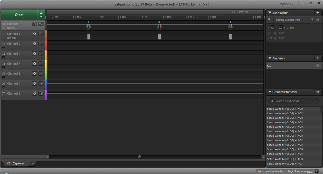
With Arduino, MCP Works properly able to do i2c, SET & GET DATETIME
Arduino Code:
#include <Wire.h>


void setup()
{
  Wire.begin();

  Serial.begin(115200);
  while (!Serial);             // Leonardo: wait for serial monitor
  Serial.println("\nI2C Scanner");
}


void loop()
{
  byte error, address;
  int nDevices;

  Serial.println("Scanning...");

  nDevices = 0;
  //for(address = 1; address < 127; address++ )
  while(1)
  {
//SENDING 0x6F in decimal as per arduino Wire library
    Wire.beginTransmission(111);
    error = Wire.endTransmission();

    if (error == 0)
    {
      Serial.print("I2C device found at address 0x");
      if (address<16)
        Serial.print("0");
      Serial.print(address,HEX);
      Serial.println("  !");

      nDevices++;
    }
    else if (error==4)
    {
      Serial.print("Unknown error at address 0x");
      if (address<16)
        Serial.print("0");
      Serial.println(address,HEX);
    }
  }
  if (nDevices == 0)
    Serial.println("No I2C devices found\n");
  else
    Serial.println("done\n");

  //delay(5000);           // wait 5 seconds for next scan
}
Please reply for a possible way of the solution!
With the Arduino you are writting to a device with address 0x6F, not reading from it. So if you want to do exactly the same with the nRF52840, then you need to replace nrf_drv_twi_rx with nrf_drv_twi_tx.
Please check the traces after code updates:
    twi_init();

//    for (address = 1; address <= TWI_ADDRESSES; address++)
//    {
				while(1)
				{
					//	nrf_gpio_pin_write(RED_LED,1);
        err_code = nrf_drv_twi_tx(&m_twi, 0x6F, &sample_data, sizeof(sample_data),1);
        if (err_code == NRF_SUCCESS)
        {
            detected_device = true;
            NRF_LOG_INFO("TWI device detected at address 0x%x.\r\n", address);
						//nrf_gpio_pin_write(RED_LED,0);

        }
        NRF_LOG_FLUSH();
			}


    if (!detected_device)
    {
        NRF_LOG_INFO("No device was found.\r\n");
        NRF_LOG_FLUSH();
    }
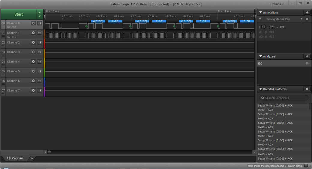
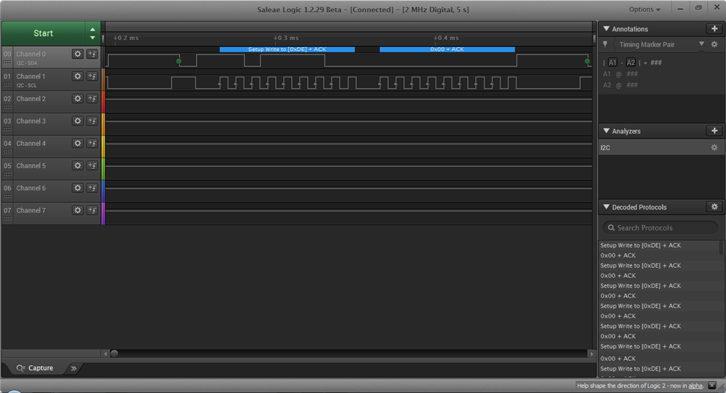
All write transactions are now followed by an ACK, which means that the MCP7940 is responding correctly. You could now try to send the I2C transaction that returns the time from the MCP7940.
Hi,
I am trying to do init sequence but not able to START Clock Oscillator of MCP7940
void init_MCP7940() {
char registerValue = 0x00; // Holds the received register value
char twelveHour = 0x00; // 0 = 24 Hour Clock Mode / 1 = 12 Hour Clock Mode
char startClock = 0x01; // 0 = Start Oscillator / 1 = Stop Oscillator
// Turn on/off: 12 hour vs. 24 hour clock
err_code = nrf_drv_twi_tx(&m_twi,MCP7940_I2C, REG_RTCHOUR, 1);
err_code = nrf_drv_twi_rx(&m_twi, MCP7940_I2C, registerValue, sizeof(MCP7940_I2C));
if (twelveHour == 0x00) err_code = nrf_drv_twi_tx(&m_twi,MCP7940_I2C, REG_RTCHOUR, bitClear (registerValue, 6));
if (twelveHour == 0x01) err_code = nrf_drv_twi_tx(&m_twi,MCP7940_I2C, REG_RTCHOUR, bitSet (registerValue, 6));
// Turn on/off: Oscillator (starts the clock)
err_code = nrf_drv_twi_rx(&m_twi, MCP7940_I2C, registerValue, 1);
if (startClock == 0x00) err_code = nrf_drv_twi_tx(&m_twi,MCP7940_I2C, REG_RTCSEC, bitClear (registerValue, 7));
if (startClock == 0x01) err_code = nrf_drv_twi_tx(&m_twi,MCP7940_I2C, REG_RTCSEC, bitSet (registerValue, 7));
}
Please attach a logic trace of the I2C lines when you run the init_MCP7940() function.