Hi everyone,
We need your help with a condition that we encountered in our prototype of a nRF52840 that use a ceramic antenna. Our current design is poor and we will have migrate eventually to the PCB trace antenna. But we need to understand whats going on here. Our design was based on the hardware documentation of Nordic "nrf52840_qiaa_var5_schematic.pdf" with a little twist in order to use a ceramic antenna, keeping the LC matching components as you can see int the schematic design.

Schematic design.
 }
}
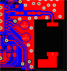
Board PCB Design, 2 layers, 1.6mm height.
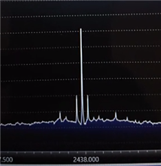
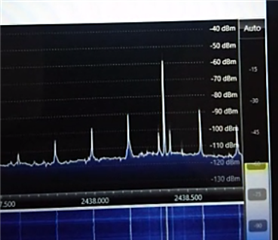
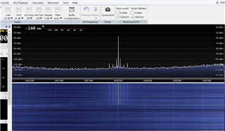
We run the board with a Radio firmware tuned on 2.438 GHz and we see the signal with a lot of harmonics but also shifted, and this is the actual issue that we need to understand. We compare the nRF52840DK board with our design, and the difference are obvious.

nRF52840DK with radio test 2.438 GHz

Prototype board with radio test 2.438 GHz
Can you help us with any observation or if you found other cases or design with similar behavior?
PD: Sorry for the quality of the screenshots.
Thanks in advance.
Rvc.


