This post is older than 2 years and might not be relevant anymore
More Info: Consider searching for newer posts

How can I set the trigger of the adxl362 to a specific value?

Hi, I am working with the adxl362 sensor on the Thingy91 and I want to set the trigger of the sensor to a specific value. 

In the datasheet (https://www.analog.com/media/en/technical-documentation/data-sheets/ADXL362.pdf), it says that the threshold should be adjustable. In the Zephyr Documentation (https://docs.zephyrproject.org/latest/reference/peripherals/sensor.html), I found that there is a SENSOR_TRIG_THRESHOLD and that it can be configurated with  SENSOR_ATTR_LOWER_THRESH and SENSOR_ATTR_UPPER_THRESH, but I have no idea how to use them in the code. Does someone could give me an example code line on how to set the trigger?

Thanks for your help!

Parents Reply Children
  • Hi, thanks for your code example. I am now able to read the registers too. 

    How did you managed to write the registers? 

    void spi_test_send(void)
    {
    	int err;
    	static u8_t tx_buffer[1] = {0x0F};
    	static u8_t rx_buffer[2]= {0x0A, 0x20};
    
            gpio_pin_write(cs_gpio, cd_pin, 0);
    
    
    	const struct spi_buf tx_buf = {
    		.buf = tx_buffer,
    		.len = sizeof(tx_buffer)
    	};
    	const struct spi_buf_set tx = {
    		.buffers = &tx_buf,
    		.count = 1
    	};
    
    	struct spi_buf rx_buf = {
    		.buf = rx_buffer,
    		.len = sizeof(rx_buffer),
    	};
    	const struct spi_buf_set rx = {
    		.buffers = &rx_buf,
    		.count = 1
    	};
    
    	err = spi_transceive(spi_dev, &spi_cfg, &tx, &rx);
    	if (err) {
    		printk("SPI error: %d\n", err);
    	} else {
    		/* Connect MISO to MOSI for loopback */
    		printk("TX sent: %x\n", tx_buffer[0]);
    		printk("RX recv: %x\n", rx_buffer[0]);
    	}
            gpio_pin_write(cs_gpio, cd_pin, 1);
    }

    I wanted to try to write the 0x20 (Lower Threshold) with the value 0x0F with the code above.

    Do I have to add the 0x0A? Or how do I have to write these two lines correctly then?:

    static u8_t tx_buffer[1] = {0x0F};
    static u8_t rx_buffer[2]= {0x0A, 0x20};

    Do I need here the 

    gpio_pin_write(cs_gpio, cd_pin, 0);
    gpio_pin_write(cs_gpio, cd_pin, 1);

    like in the read function?

    Thanks for your help and your answers!

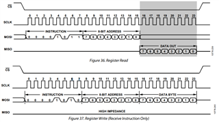
  • I solved it by my own with the help of the timing diagram:

    I have a working code for the read area of the diagram and I need a code that works for the write area of the diagram. I need to expand the buffer and send 3 bytes instead of 2. The working code is:

    void spi_write_reg(void)
    {
      u8_t cmd =      0x0A;
      u8_t reg_addr = 0x20; // register, that you want to write
      u8_t value = 0x46; // value, that you want to set
      void *data = &value;
      int length = 1;
    	u8_t access[3] = { cmd, reg_addr, value };
    
      gpio_pin_write(cs_gpio, cd_pin, 0);
    
    	const struct spi_buf buf[2] = {
    		{
    			.buf = access,
    			.len = 3
    		},
    		{
    			.buf = data,
    			.len = length
    		}
    	};
    	struct spi_buf_set tx = {
    		.buffers = buf,
    	};
    
    
    	const struct spi_buf_set rx = {
    		.buffers = buf,
    		.count = 2
    	};
    
    	tx.count = 1;
    
    	int spi_result = spi_transceive(spi_dev, &spi_cfg, &tx, &rx);
    
     // printk("SPI result: %d\n",spi_result);
      printk("Value: 0x%02X\n", value);
    
      gpio_pin_write(cs_gpio, cd_pin, 1);
    
    }

Related