This post is older than 2 years and might not be relevant anymore
More Info: Consider searching for newer posts

How can I set the trigger of the adxl362 to a specific value?

Hi, I am working with the adxl362 sensor on the Thingy91 and I want to set the trigger of the sensor to a specific value. 

In the datasheet (https://www.analog.com/media/en/technical-documentation/data-sheets/ADXL362.pdf), it says that the threshold should be adjustable. In the Zephyr Documentation (https://docs.zephyrproject.org/latest/reference/peripherals/sensor.html), I found that there is a SENSOR_TRIG_THRESHOLD and that it can be configurated with  SENSOR_ATTR_LOWER_THRESH and SENSOR_ATTR_UPPER_THRESH, but I have no idea how to use them in the code. Does someone could give me an example code line on how to set the trigger?

Thanks for your help!

Parents
  • Hello, 
     

    Does someone could give me an example code line on how to set the trigger?

    Have a look at our BH1749 sample (nrf\samples\sensor\bh1749), and the ADXL362 drivers found here: zephyr\drivers\sensor\adxl362\

    Kind regards,
    Øyvind

  • Hi, sorry for the delay.

    That doesn't really work, my skills are not good enough.

    Do you maybe have a example code, where you write the register of the adxl362 or another sensor? 

    I tried to import the driver files in zephyr\drivers\sensor\adxl362\, but when I wanted to write a register, I got an spi error. So could you maybe provide an example program? 


    Thanks for your help!

  • Hi there,

    I had a similar issue in the past with the ADXL362. Have a look at this thread and try running the example code I listed there. You should be able to read the ADXL362's part ID. From that you should be able to start reading through the Datasheet and building you application. devzone.nordicsemi.com/.../how-to-get-accelerometer-value-of-thingy-91

  • Hi, thanks for your code example. I am now able to read the registers too. 

    How did you managed to write the registers? 

    void spi_test_send(void)
    {
    	int err;
    	static u8_t tx_buffer[1] = {0x0F};
    	static u8_t rx_buffer[2]= {0x0A, 0x20};
    
            gpio_pin_write(cs_gpio, cd_pin, 0);
    
    
    	const struct spi_buf tx_buf = {
    		.buf = tx_buffer,
    		.len = sizeof(tx_buffer)
    	};
    	const struct spi_buf_set tx = {
    		.buffers = &tx_buf,
    		.count = 1
    	};
    
    	struct spi_buf rx_buf = {
    		.buf = rx_buffer,
    		.len = sizeof(rx_buffer),
    	};
    	const struct spi_buf_set rx = {
    		.buffers = &rx_buf,
    		.count = 1
    	};
    
    	err = spi_transceive(spi_dev, &spi_cfg, &tx, &rx);
    	if (err) {
    		printk("SPI error: %d\n", err);
    	} else {
    		/* Connect MISO to MOSI for loopback */
    		printk("TX sent: %x\n", tx_buffer[0]);
    		printk("RX recv: %x\n", rx_buffer[0]);
    	}
            gpio_pin_write(cs_gpio, cd_pin, 1);
    }

    I wanted to try to write the 0x20 (Lower Threshold) with the value 0x0F with the code above.

    Do I have to add the 0x0A? Or how do I have to write these two lines correctly then?:

    static u8_t tx_buffer[1] = {0x0F};
    static u8_t rx_buffer[2]= {0x0A, 0x20};

    Do I need here the 

    gpio_pin_write(cs_gpio, cd_pin, 0);
    gpio_pin_write(cs_gpio, cd_pin, 1);

    like in the read function?

    Thanks for your help and your answers!

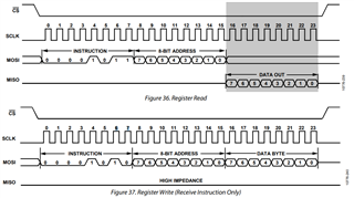
  • I solved it by my own with the help of the timing diagram:

    I have a working code for the read area of the diagram and I need a code that works for the write area of the diagram. I need to expand the buffer and send 3 bytes instead of 2. The working code is:

    void spi_write_reg(void)
    {
      u8_t cmd =      0x0A;
      u8_t reg_addr = 0x20; // register, that you want to write
      u8_t value = 0x46; // value, that you want to set
      void *data = &value;
      int length = 1;
    	u8_t access[3] = { cmd, reg_addr, value };
    
      gpio_pin_write(cs_gpio, cd_pin, 0);
    
    	const struct spi_buf buf[2] = {
    		{
    			.buf = access,
    			.len = 3
    		},
    		{
    			.buf = data,
    			.len = length
    		}
    	};
    	struct spi_buf_set tx = {
    		.buffers = buf,
    	};
    
    
    	const struct spi_buf_set rx = {
    		.buffers = buf,
    		.count = 2
    	};
    
    	tx.count = 1;
    
    	int spi_result = spi_transceive(spi_dev, &spi_cfg, &tx, &rx);
    
     // printk("SPI result: %d\n",spi_result);
      printk("Value: 0x%02X\n", value);
    
      gpio_pin_write(cs_gpio, cd_pin, 1);
    
    }

Reply
  • I solved it by my own with the help of the timing diagram:

    I have a working code for the read area of the diagram and I need a code that works for the write area of the diagram. I need to expand the buffer and send 3 bytes instead of 2. The working code is:

    void spi_write_reg(void)
    {
      u8_t cmd =      0x0A;
      u8_t reg_addr = 0x20; // register, that you want to write
      u8_t value = 0x46; // value, that you want to set
      void *data = &value;
      int length = 1;
    	u8_t access[3] = { cmd, reg_addr, value };
    
      gpio_pin_write(cs_gpio, cd_pin, 0);
    
    	const struct spi_buf buf[2] = {
    		{
    			.buf = access,
    			.len = 3
    		},
    		{
    			.buf = data,
    			.len = length
    		}
    	};
    	struct spi_buf_set tx = {
    		.buffers = buf,
    	};
    
    
    	const struct spi_buf_set rx = {
    		.buffers = buf,
    		.count = 2
    	};
    
    	tx.count = 1;
    
    	int spi_result = spi_transceive(spi_dev, &spi_cfg, &tx, &rx);
    
     // printk("SPI result: %d\n",spi_result);
      printk("Value: 0x%02X\n", value);
    
      gpio_pin_write(cs_gpio, cd_pin, 1);
    
    }

Children
No Data
Related