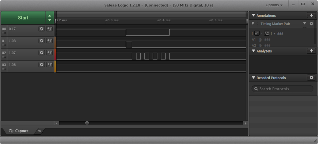
I have an issue with getting the I/Os correctly setup for antenna switching.
I am running the radio_test example code with the following modifications.
So far, I have the following code for the GPIO setup:
//Defines are at top of file
#define ANT1 NRF_GPIO_PIN_MAP(0,17)
#define ANT2 NRF_GPIO_PIN_MAP(1,8)
#define ANT3 NRF_GPIO_PIN_MAP(1,7)
#define ANT4 NRF_GPIO_PIN_MAP(1,6)

//other support code

//Pin config
nrf_gpio_pin_clear(ANT1);
nrf_gpio_cfg_output(ANT1);
nrf_gpio_pin_clear(ANT2);
nrf_gpio_cfg_output(ANT2);
nrf_gpio_pin_clear(ANT3);
nrf_gpio_cfg_output(ANT3);
nrf_gpio_pin_clear(ANT4);
nrf_gpio_cfg_output(ANT4);

//DFE pin config
NRF_RADIO->PSEL.DFEGPIO[0] = ANT1; //(P0.17)
NRF_RADIO->PSEL.DFEGPIO[1] = ANT2; //(P1.08)
NRF_RADIO->PSEL.DFEGPIO[2] = ANT3; //(P1.07)
NRF_RADIO->PSEL.DFEGPIO[4] = ANT4; //(P1.06)

NRF_RADIO->SWITCHPATTERN = 1; //Only P0.07 active
NRF_RADIO->SWITCHPATTERN = 2; //Only P1.08 active
NRF_RADIO->SWITCHPATTERN = 4; //Only P1.07 active
NRF_RADIO->SWITCHPATTERN = 8; //Only P1.06 active

NRF_RADIO->DFEMODE = RADIO_DFEMODE_DFEOPMODE_AoA;
NRF_RADIO->DFECTRL1 = 10 << RADIO_DFECTRL1_NUMBEROF8US_Pos |
                       1 << RADIO_DFECTRL1_DFEINEXTENSION_Pos;
Then in the radio_test.c file, I include in the function radio_rx( ...)
uint32_t g_iq_packet[RADIO_MAX_PAYLOAD_LEN];

void radio_rx(....)
{
//orig example code still exists here, only not shown
    NRF_RADIO->DFEPACKET.PTR = (uint32_t)g_iq_packet;

}
From a board running the radio_test example, I issue the 'start_tx_modulated_carrier' command the immediately issue the 'start_rx" command on a seperate DK also running the radio_test example with the above modifications.
I expected to see a short duration square wave on each of the antenna GPIO pins, so, 4 square waves cascading in time. However from my logic analyzer capture, you can clearly see that is not the case.
How should I be setting up the config registers to fire each of the pins. Nothing else is connected to the board except the logic analyzer.
Also, how do I correlate the IQ data from the DFEPACKET.PTR to the specific antenna?


