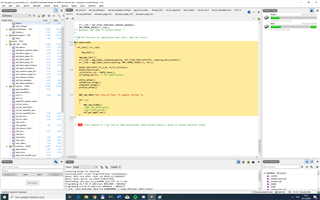
Hi,
I am working with ANT bpwr tx profile and trying to implement HX711 and TWI sensor to it. TWI sensor is already working, but when I add library for HX711 from Vidar Berg and start sampling HX711, the ant transmission looks like it stops transmitting, or lose all packets. I can see it in AntWare II, that when hx711_start(false) function is called, AntWare can not see any transmitting device and i can see data from hx711 printing in debug terminal, but when I comment this function and let it how it was before, AntWare II can see the device and is able to receive data, so i know, that there is some conflict between hx711 data sampling and ant+ data transmission, but the project compiles succesfull. Do somebody know, what might be the problem?
using nRF52832, SDK15.2, Segger embedded studio, and library written by Vidar
thanks in advance
/******************************************************************************/
/*                                                                            */
/******************************************************************************/

#include <stdint.h>
#include <string.h>
#include "hx711.h"
#include "nrf_drv_gpiote.h"
#include "app_util_platform.h"
#include "boards.h"
#include "nrf_delay.h"

#define NRF_LOG_MODULE_NAME hx711

#if HX711_CONFIG_LOG_ENABLED
    #define NRF_LOG_LEVEL           HX711_CONFIG_LOG_LEVEL
    #define NRF_LOG_INFO_COLOR      HX711_CONFIG_INFO_COLOR
    #define NRF_LOG_DEBUG_COLOR     HX711_CONFIG_DEBUG_COLOR
#else // HX711_CONFIG_LOG_ENABLED
    #define NRF_LOG_LEVEL           0
#endif  // HX711_CONFIG_LOG_ENABLED
#include "nrf_log.h"
NRF_LOG_MODULE_REGISTER();

/* Defines frequency and duty cycle for clock signal - default: 1 MHz 50%*/
#define TIMER_COUNTERTOP          32
#define TIMER_COMPARE             16

// Pinout
#define PD_SCK                    23
#define DOUT                      24
#define VDD                       25  // Note: Depending on design, GPIO may not be able to source enough current for hx711 and loadcell.

/* HX711 ADC resolution in bits */
#define ADC_RES                   24

typedef  struct
{
   uint32_t   value;   // buffer for ADC read
   uint8_t    count;   // number of bitshifts. Read complete when count == ADC_RES
}hx711_sample_t;

static volatile hx711_sample_t                    m_sample;
static hx711_event_handler_t                      m_evt_handler;
static uint32_t                                   m_mode;
static bool                                       m_continous_sampling;


static int convert_sample(uint32_t sample)
{
  return (int)(sample << 8) >> 8;
}


/* Clocks out HX711 result - if readout fails consistently, try to increase the clock period and/or enable compiler optimization */
static void hx711_sample()
{
    NRF_TIMER2->TASKS_CLEAR = 1;
    m_sample.count = 0;
    m_sample.value = 0;
    NRF_TIMER1->TASKS_START = 1; // Starts clock signal on PD_SCK

    for (uint32_t i=0; i < ADC_RES; i++)
    {
        do
        {
            /* NRF_TIMER->CC[1] contains number of clock cycles.*/
            NRF_TIMER2->TASKS_CAPTURE[1] = 1;
            if (NRF_TIMER2->CC[1] >= ADC_RES) goto EXIT; // Readout not in sync with PD_CLK. Abort and notify error.
        }
        while(NRF_TIMER1->EVENTS_COMPARE[0] == 0);
        NRF_TIMER1->EVENTS_COMPARE[0] = 0;
        m_sample.value |= (nrf_gpio_pin_read(DOUT) << (23 - i));
        m_sample.count++;
    }
    EXIT:

    if (!m_continous_sampling)
    {
        NRF_GPIOTE->TASKS_SET[1] = 1; // HX711 power-down
    }

    NRF_LOG_INFO("Number of bits : %d", m_sample.count);
    NRF_LOG_INFO("ADC val: 0x%x", m_sample.value);

    if (m_sample.count == ADC_RES)
    {
        // Send notification with raw ADC value
        m_evt_handler(DATA_READY, convert_sample(m_sample.value));
    }
    else
    {
       // Notify readout error
       m_evt_handler(DATA_ERROR, m_sample.value);
    }

}


static void gpiote_evt_handler(nrf_drv_gpiote_pin_t pin, nrf_gpiote_polarity_t action)
{
    nrf_drv_gpiote_in_event_disable(DOUT);
    hx711_sample();

    if (m_continous_sampling)
    {
       nrf_drv_gpiote_in_event_enable(DOUT, true);
    }
}


void hx711_init(hx711_mode_t mode, hx711_event_handler_t evt_handler)
{

  ret_code_t                  ret_code;
  nrf_drv_gpiote_in_config_t  gpiote_config = GPIOTE_CONFIG_IN_SENSE_HITOLO(false);

  m_evt_handler = evt_handler;
  m_mode = mode;

  nrf_gpio_cfg_output(PD_SCK);
  nrf_gpio_pin_set(PD_SCK);

  nrf_gpio_cfg(VDD,
               NRF_GPIO_PIN_DIR_OUTPUT,
               NRF_GPIO_PIN_INPUT_DISCONNECT,
               NRF_GPIO_PIN_PULLUP,
               NRF_GPIO_PIN_S0H1,
               NRF_GPIO_PIN_NOSENSE);
  nrf_gpio_pin_set(VDD);

  nrf_gpio_cfg_input(DOUT, NRF_GPIO_PIN_NOPULL);

  if (!nrf_drv_gpiote_is_init())
  {
    ret_code = nrf_drv_gpiote_init();
    APP_ERROR_CHECK(ret_code);
  }

  ret_code = nrf_drv_gpiote_in_init(DOUT, &gpiote_config, gpiote_evt_handler);
  APP_ERROR_CHECK(ret_code);

  /* Set up timers, gpiote, and ppi for clock signal generation*/
  NRF_TIMER1->CC[0]     = 1;
  NRF_TIMER1->CC[1]     = TIMER_COMPARE;
  NRF_TIMER1->CC[2]     = TIMER_COUNTERTOP;
  NRF_TIMER1->SHORTS    = (uint32_t) (1 << 2);    //COMPARE2_CLEAR
  NRF_TIMER1->PRESCALER = 0;

  NRF_TIMER2->CC[0]     = m_mode;
  NRF_TIMER2->MODE      = 2;

  NRF_GPIOTE->CONFIG[1] = (uint32_t) (3 | (PD_SCK << 8) | (1 << 16) | (1 << 20));

  NRF_PPI->CH[0].EEP   = (uint32_t) &NRF_TIMER1->EVENTS_COMPARE[0];
  NRF_PPI->CH[0].TEP   = (uint32_t) &NRF_GPIOTE->TASKS_SET[1];
  NRF_PPI->CH[1].EEP   = (uint32_t) &NRF_TIMER1->EVENTS_COMPARE[1];
  NRF_PPI->CH[1].TEP   = (uint32_t) &NRF_GPIOTE->TASKS_CLR[1];
  NRF_PPI->FORK[1].TEP = (uint32_t) &NRF_TIMER2->TASKS_COUNT; // Increment on falling edge
  NRF_PPI->CH[2].EEP   = (uint32_t) &NRF_TIMER2->EVENTS_COMPARE[0];
  NRF_PPI->CH[2].TEP   = (uint32_t) &NRF_TIMER1->TASKS_SHUTDOWN;
  NRF_PPI->CHEN = 7;
}


void hx711_power_down()
{
   nrf_gpio_cfg_default(VDD);
   nrf_gpio_cfg_default(PD_SCK);
   nrf_gpio_cfg_default(DOUT);
}

void hx711_start(bool single)
{

    m_continous_sampling = !single;

    NRF_LOG_INFO("Start sampling");

    NRF_GPIOTE->TASKS_CLR[1] = 1;
    // Generates interrupt when new sampling is available.
    nrf_drv_gpiote_in_event_enable(DOUT, true);
}

void hx711_stop()
{
    nrf_drv_gpiote_in_event_disable(DOUT);
    NRF_GPIOTE->TASKS_SET[1] = 1; // Must be kept high for >60 us to power down HX711
}


