
Hello,
Our team is new on development nRF52832 firmware.
Now we have an issue on standby current for nRF52832.
We have a 5 second timer for a PWM output.
Sleep (System on, 32768Hz crystal) for 4 seconds -> wake up & battery level ADC + PWM output 1 second -> sleep again and loop
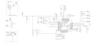
Here is the schematic:
Now, we get 0.5mA current while in the 4 second sleep time.
Is it totally not reasonable? it won't be such high, right?
Any idea or hint to me?
And is it possible to provide me any sample code / hex file (system on sleep mode) to me, so that i can download to my PCB to measure standby current for verification?
Thank you very much & Sorry for newbie here.

