This post is older than 2 years and might not be relevant anymore
More Info: Consider searching for newer posts

odd phase transitions in direction finding MagPhase mode

Hi,

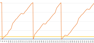
I have test setup consisting of 2 boards, one that sends a packet every 2 seconds with CTE, and another with a 2-antenna array that generates MagPhase samples and sends them to a serial port so that I can save and plot them. I'm running in AoA mode, switching between the 2 antennas every 4us. I am sampling every 125ns, so I get 32 samples on each antenna. I'm keeping the sample rate high for now so that I can see the phase slope shifting as I move the transmitter.

My question concerns the phase changes around the antenna switch events. I expected to see a fairly obvious jump in the phase, especially as the 125ns sample period is much longer than the 10-20ns or so switch-over that my switch should have (using a HMC194AMS8E), and the rise and fall time of the control lines are approx.10ns. Instead I am seeing what looks like a filtered transition, spread over approx 12 samples, or 1.5us, like this:

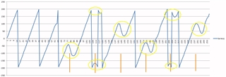
The orange lines correspond to the switch transition points, roughly.

Does anyone have an explanation for this? Is it something to do with how the phase is calculated from the IQ samples? 

Thanks

Pete

Parents
  • Hi Peter, 

    As far as I have understood, this is expected. This is a comment that one of the R&D engineers working on the Direction Finding features of our RADIO gave on a similiar case. The customer was using the following setup:

    Switching between antenna A1 and A2 beginning with A1 for guard, ref and as first antenna then A2 etc.
    2us switching spacing
    288 I/Q samples in total starting with I1 and then Q1, I2, Q2 etc
    5*8us in total including guard and ref
    125ns sampling during ref and normal
    Ch 38 ie.e 2426 MHz

    The distance between the first sample recorded in the REFERENCE state and the first sample recorded in the SWITCHING state will be the same independently of TSAMPLINGREF and TSAMPLING

    The reason for this is that it should be possible to change the sampling rate in the REFERENCE state without affecting the sampling times in the SWITCHING state.

    The distance between the last sample in the REFERENCE state and the first sample in the SWITCHING state is dependent on TSWITCHSPACING. It is such that the first SWITCHING sample will be taken in the first SAMPLING slot. So, since the switch spacing is 2us in the customer's case, the first SAMPLING slot will be 1us into the SWITCHING state. 

    Best regards

    Bjørn

  • Hi Bjørn,

    Thanks for the reply but I think my question has been misunderstood. I realise that there is always a shift between the end of the reference period and the first sample in the switching slot, but I'm I'm referring to the shape of the phase that I'm seeing at all switching transitions. My selected RF switch is supposed to have a settling time of around 10ns, so I expect to see clean phase changes at the transitions (as the path lengths to my 2 antennas are different) but I see a very slow, distorted transition, lasting almost 1.5us, which I've circled in yellow in the figure in my original post. I've tried changing the drive to my switch control lines, and reducing decoupling capacitors etc. but nothing improves it. I'm wondering what is causing it. I expect to see something more like this, which Dmitry posted elsewhere:

    Regards

    Pete

Reply
  • Hi Bjørn,

    Thanks for the reply but I think my question has been misunderstood. I realise that there is always a shift between the end of the reference period and the first sample in the switching slot, but I'm I'm referring to the shape of the phase that I'm seeing at all switching transitions. My selected RF switch is supposed to have a settling time of around 10ns, so I expect to see clean phase changes at the transitions (as the path lengths to my 2 antennas are different) but I see a very slow, distorted transition, lasting almost 1.5us, which I've circled in yellow in the figure in my original post. I've tried changing the drive to my switch control lines, and reducing decoupling capacitors etc. but nothing improves it. I'm wondering what is causing it. I expect to see something more like this, which Dmitry posted elsewhere:

    Regards

    Pete

Children
Related