This post is older than 2 years and might not be relevant anymore
More Info: Consider searching for newer posts

Problems with Flashing and GPIO enabling | nRF52840

Dear All,

    I am using  (nRF52840) in one of my design. 


     Application program we have taken examples\peripheral\usbd_ble_uart\pca10056\s140\arm5_no_packs code as base code.


    - Flashing a NEW CHIP first time Booting never happens

           Made a new board and flashing the chip first time it never gets booted.  Couple of boards i flashed some random program from example and then if i flash the actual application programs it will run.  Currently the random flashing also not giving solution.


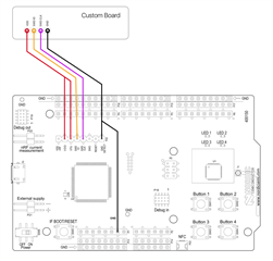
          Kindly provide an example program or steps to flash the new chip.


    - GPIO program kindly verify if below initialisation is enough.


          problem here is other than P0.06 every other GPIO is working fine.  Pls guide if any issue from our initialisation.


#define S32_SPIS_CS_PIN            NRF_GPIO_PIN_MAP(0,6) 
#define S32_SPIS_MISO_PIN NRF_GPIO_PIN_MAP(0,8)
#define S32_SPIS_MOSI_PIN NRF_GPIO_PIN_MAP(0,4)
#define S32_SPIS_SCK_PIN NRF_GPIO_PIN_MAP(0,12)
#define S32_BT_INT_PIN NRF_GPIO_PIN_MAP(1,9)

nrf_gpio_cfg_output (S32_SPIS_CS_PIN);
nrf_gpio_cfg_output (S32_SPIS_MISO_PIN);
nrf_gpio_cfg_output (S32_SPIS_MOSI_PIN);
nrf_gpio_cfg_output (S32_SPIS_SCK_PIN);
nrf_gpio_cfg_output (S32_BT_INT_PIN);


while(1){
#if 1
nrf_gpio_pin_set (S32_SPIS_CS_PIN);
nrf_delay_ms(5);

nrf_gpio_pin_set (S32_SPIS_MISO_PIN);
nrf_delay_ms(5);

nrf_gpio_pin_set (S32_SPIS_MOSI_PIN);
nrf_delay_ms(5);

nrf_gpio_pin_set (S32_SPIS_SCK_PIN);
nrf_delay_ms(5);

nrf_gpio_pin_set (S32_BT_INT_PIN);
nrf_delay_ms(50);

nrf_gpio_pin_clear (S32_SPIS_CS_PIN);
nrf_delay_ms(5);

nrf_gpio_pin_clear (S32_SPIS_MISO_PIN);
nrf_delay_ms(5);

nrf_gpio_pin_clear (S32_SPIS_MOSI_PIN);
nrf_delay_ms(5);

nrf_gpio_pin_clear (S32_SPIS_SCK_PIN);

nrf_delay_ms(5);

nrf_gpio_pin_clear (S32_BT_INT_PIN);
nrf_delay_ms(50);
#endif

Parents
  • Hi

    The GPIO issue is pretty straight-forward I think. If you have enabled debug logging P0.06 is the default pin for sending data to the debugger.

    As for the flashing issue, I think I'll need some more information. Are you using an nRF52840 DK as a debugger or another JLink device? Do you have to flash the same code twice every time in order for it to run on your device? What do you mean by "Currently the random flashing also not giving solution."?

    Please confirm that your custom board is connected to the debugger like this if you're not using a 10pin debug cable:

    Best regards,

    Simon

  • Hi Simon,

    Thanks.

    Yes disabling the UART debugging in sdk_config.h i am able to use the GPIO mode,which i used for SPI communication ie P0.06, P0.08, P0.04 and p0.12.


    But I am struck with P1.09, this is not working as GPIO, but it's not a blocking issue now as we are using this as INTERRUPT to main controller.


    Above all we done to check the PCB connectivity check to controller, purpose is to use all the above mentioned GPIO as SPI lines as mentioned below:


    #define S32_SPIS_CS_PIN           NRF_GPIO_PIN_MAP(0,6) //231 y
    #define S32_SPIS_MISO_PIN         NRF_GPIO_PIN_MAP(0,8)//235  y
    #define S32_SPIS_MOSI_PIN         NRF_GPIO_PIN_MAP(0,4) //230  y
    #define S32_SPIS_SCK_PIN          NRF_GPIO_PIN_MAP(0,12) //237  y
     

    But for SPI communication 


    #define  S32_SPIS_CS_PIN        6  //P0.06
    #define  S32_SPIS_MISO_PIN    8  //P0.08
    #define  S32_SPIS_MOSI_PIN    4  //P0.04
    #define  S32_SPIS_SCK_PIN     12 //P0.12


    #define S32_BT_INT_PIN            NRF_GPIO_PIN_MAP(1,9) //241  not able to work as GPIO 


        nrf_drv_spis_config_t spis_config = NRF_DRV_SPIS_DEFAULT_CONFIG;
        spis_config.csn_pin               = S32_SPIS_CS_PIN;
        spis_config.miso_pin              = S32_SPIS_MISO_PIN;
        spis_config.mosi_pin              = S32_SPIS_MOSI_PIN;
        spis_config.sck_pin               = S32_SPIS_SCK_PIN;

        APP_ERROR_CHECK(nrf_drv_spis_init(&spis, &spis_config, spis_event_handler)   );


        Kindly guide on SPI interface and P1.09 as GPIO.

Reply
  • Hi Simon,

    Thanks.

    Yes disabling the UART debugging in sdk_config.h i am able to use the GPIO mode,which i used for SPI communication ie P0.06, P0.08, P0.04 and p0.12.


    But I am struck with P1.09, this is not working as GPIO, but it's not a blocking issue now as we are using this as INTERRUPT to main controller.


    Above all we done to check the PCB connectivity check to controller, purpose is to use all the above mentioned GPIO as SPI lines as mentioned below:


    #define S32_SPIS_CS_PIN           NRF_GPIO_PIN_MAP(0,6) //231 y
    #define S32_SPIS_MISO_PIN         NRF_GPIO_PIN_MAP(0,8)//235  y
    #define S32_SPIS_MOSI_PIN         NRF_GPIO_PIN_MAP(0,4) //230  y
    #define S32_SPIS_SCK_PIN          NRF_GPIO_PIN_MAP(0,12) //237  y
     

    But for SPI communication 


    #define  S32_SPIS_CS_PIN        6  //P0.06
    #define  S32_SPIS_MISO_PIN    8  //P0.08
    #define  S32_SPIS_MOSI_PIN    4  //P0.04
    #define  S32_SPIS_SCK_PIN     12 //P0.12


    #define S32_BT_INT_PIN            NRF_GPIO_PIN_MAP(1,9) //241  not able to work as GPIO 


        nrf_drv_spis_config_t spis_config = NRF_DRV_SPIS_DEFAULT_CONFIG;
        spis_config.csn_pin               = S32_SPIS_CS_PIN;
        spis_config.miso_pin              = S32_SPIS_MISO_PIN;
        spis_config.mosi_pin              = S32_SPIS_MOSI_PIN;
        spis_config.sck_pin               = S32_SPIS_SCK_PIN;

        APP_ERROR_CHECK(nrf_drv_spis_init(&spis, &spis_config, spis_event_handler)   );


        Kindly guide on SPI interface and P1.09 as GPIO.

Children
No Data
Related