Hello,
it would seem that the Spi Slave example provided with the SDK 12.3.0 does not work correctly for the nRF51DK.
Setup:
Master SPI : STM30G070CB
Slave SPI : nF51DK
SDK : 12.3.0
BaudRate : 62.5 KBits/s
I am using the spi slave example except for the data to transmit back which have been changed :
#define TEST_STRING {'R','o','g','e','r'}
static uint8_t m_tx_buf[5] = TEST_STRING; /**< TX buffer. */
static uint8_t m_rx_buf[5]; /**< RX buffer. */
static const uint8_t m_length = sizeof(m_tx_buf); /**< Transfer length. */
So as you can see, the only thing I changed is the message sent back to the master SPI, as well as the buffer of the received message.
The SPI slave can receive the data correctly. I alternate between 'Allo!' and 'Bueno' in an indefinite loop to make sure that the message transition correctly.
However, when the data is received, the slave does not respond back with 'Roger' as it should.

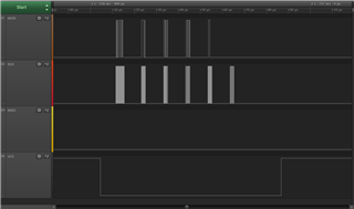
As you can see on the screenshot above, the master SPI is sending either 'Allo!' or 'Bueno' and is expecting 5 characters backs ; the clock is the same length as the first 5 characters, with a clock pause of around 30 usec between the data sent by the master, and the master expecting data back.
When I look at the SPIS document on infocenter, there is no explanation of how the SPIS module works for the nRF51822. The product specification section on the SPI/SPIS is only a paragraph long and if there is any other information regarding the SPIS, it is hidden somewhere I am not aware of.
Since the example provided use easy DMA, I looked through other chips to see if any information was available and saw that the nRF52832 has a lot more explanation (it would seem like nRF52 products are a lot more detailed than nRF51, why is that? Should we use a nRF52 product instead of a nRF51?). In the SPIS section of the nRF52832 , in the slave operation section, I found this information :
If the SPI slave acquires the semaphore, the transaction will be granted. The incoming data on MOSI will be stored in the RXD buffer and the data in the TXD buffer will be clocked out on MISO.
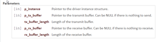
When I look through the example code, when the buffers are setup with APP_ERROR_CHECK(nrf_drv_spis_buffers_set(&spis, m_tx_buf, m_length, m_rx_buf, m_length)); , if I step into the code :
nrf_drv_spis_buffers_set -> spi_state_change -> spis_state_entry_action_execute
I can see that the SPIS module is taking the semaphore by using NRF_SPIS_TASK_ACQUIRE (nrf_spis_task_trigger(p_spis, NRF_SPIS_TASK_ACQUIRE);). Assuming that the information above about the semaphore is applicable for the nRF51822, the SPIS module should output 'Roger' on the MISO line. But, on a period of 5 seconds, the MISO line is never active once.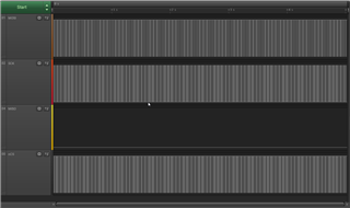
So what am I missing here? Is there any other information I should have read that I missed in the product specification because the SPI/SPIS section is pretty barren.