
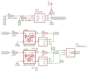
I have an application that requires mains power for lighting with a BLE receiver that is permanently advertising and scanning and I need to be able to dim the lights. My circuit uses zero-crossing and a triac to control the mains. I'm using a Fanstel BT832 module which is just the NRF52832 chip.
My code is currently based on the ble_app_interactive from the ble_central_and_peripheral examples in nRF5_SDK_16.
I've built a prototype unit that works in every respect except the dimming. The dimming is fine if I turn off advertising and scanning, but flickers when these are running. I've tried using only GPIOTE to achieve the dimming (which flickered). I then found some example code that used PPI, with 2 timer instances monitoring phase shift and pulse length, and tried this. Again the dimming works perfectly until I start the scanning or advertising.
I’ve tried the code on the NRF52-dk, which gives the same results, but have also tried the code on a Decawave DWM1001 which uses the NRF52832 and this seems to work without any flickering. I cannot see any reason for this.
I thought the lack of a crystal on the Fanstel chip may have been to blame, as the Decawave module has a crystal, but the NRF52-dk has a crystal and this still sees the flicker.
Can anyone help with how to overcome this?
const nrf_drv_timer_t phaseshift_timer  = NRF_DRV_TIMER_INSTANCE(1);
const nrf_drv_timer_t pulselength_timer = NRF_DRV_TIMER_INSTANCE(2);
static nrf_ppi_channel_t                m_zerocrossing_channel;

void zerocrossing_event_handler(nrf_drv_gpiote_pin_t pin, nrf_gpiote_polarity_t action) {}
void trigger_event_handler(nrf_timer_event_t event_type, void* p_context){}

/** @brief Function for timer initialization, which will be started by zero-crossing using PPI.
*/
static void high_resolution_timer_init(void)
{

    uint32_t err_code = NRF_SUCCESS;
    nrf_drv_timer_config_t timer_config = NRF_DRV_TIMER_DEFAULT_CONFIG;

    timer_config.frequency = NRF_TIMER_FREQ_1MHz;
    timer_config.bit_width = NRF_TIMER_BIT_WIDTH_16;
//    timer_config.interrupt_priority = NRF_APP_PRIORITY_LOW;
    timer_config.interrupt_priority = APP_IRQ_PRIORITY_LOW;

    timer_config.mode = NRF_TIMER_MODE_TIMER;
    timer_config.p_context = NULL;
    err_code = nrf_drv_timer_init(&phaseshift_timer, &timer_config, trigger_event_handler);
    APP_ERROR_CHECK(err_code);

    // 10000 cycles at 1Mhz makes 0.01 sec - the duration of one half wave at 50Hz mains AC frequency
    nrf_drv_timer_extended_compare(&phaseshift_timer, NRF_TIMER_CC_CHANNEL0, 0x2710, NRF_TIMER_SHORT_COMPARE0_CLEAR_MASK, false);
    err_code = nrf_drv_timer_init(&pulselength_timer, &timer_config, trigger_event_handler);
    APP_ERROR_CHECK(err_code);
    // the length of the triac firing pulse is 0.001 sec
    nrf_drv_timer_extended_compare(&pulselength_timer, NRF_TIMER_CC_CHANNEL0, 0x03E8, NRF_TIMER_SHORT_COMPARE0_CLEAR_MASK, false);
}
/** @brief Function for initializing the PPI peripheral.
*/
#define SAJ_PIN_IN    16
#define SAJ_PIN_OUT   20

static void peripheral_init(void)
{
    uint32_t err_code = NRF_SUCCESS;
    nrf_ppi_channel_t ppi_channel2;
    nrf_ppi_channel_t ppi_channel3;
    nrf_ppi_channel_t ppi_channel4;
    nrf_ppi_channel_t ppi_channel5;
    nrf_ppi_channel_t ppi_channel6;
    uint32_t zerocrossing_addr;
    uint32_t load_addr;

    // init the phase-shift and pulse-length timer
    high_resolution_timer_init();

    err_code = nrf_drv_ppi_init();
    APP_ERROR_CHECK(err_code);

    if (!nrf_drv_gpiote_is_init())
    {
        err_code = nrf_drv_gpiote_init();
        if(err_code != NRF_SUCCESS)
        {
            APP_ERROR_CHECK(err_code);
            return;
        }
    }

    // create the zero-crossing event
    nrf_drv_gpiote_in_config_t zero_config = GPIOTE_CONFIG_IN_SENSE_LOTOHI(true);
    zero_config.pull = NRF_GPIO_PIN_PULLUP;
    err_code = nrf_drv_gpiote_in_init(SAJ_PIN_IN, &zero_config, zerocrossing_event_handler);
    APP_ERROR_CHECK(err_code);
    zerocrossing_addr = nrf_drv_gpiote_in_event_addr_get(SAJ_PIN_IN);
    nrf_drv_gpiote_in_event_enable(SAJ_PIN_IN, true);
    // assign zero-crossing event to start of phase-shift timer
    // start timer on zero-crossing event
    err_code = nrf_drv_ppi_channel_alloc(&m_zerocrossing_channel);
    APP_ERROR_CHECK(err_code);
    err_code = nrf_drv_ppi_channel_assign(m_zerocrossing_channel,
                                          zerocrossing_addr,
                                          nrf_drv_timer_task_address_get(&phaseshift_timer, NRF_TIMER_TASK_START));
    APP_ERROR_CHECK(err_code);
    // create the load control task
    nrf_drv_gpiote_out_config_t load_config = GPIOTE_CONFIG_OUT_TASK_TOGGLE(true);
    load_config.init_state = NRF_GPIOTE_INITIAL_VALUE_LOW;
    err_code = nrf_drv_gpiote_out_init(SAJ_PIN_OUT, &load_config);
    APP_ERROR_CHECK(err_code);
    load_addr = nrf_drv_gpiote_out_task_addr_get(SAJ_PIN_OUT);
    nrf_drv_gpiote_out_task_enable(SAJ_PIN_OUT);
    // assign the end of the phase-shift timer to the load control task
    // toggle load control if timer overruns
    err_code = nrf_drv_ppi_channel_alloc(&ppi_channel2);
    APP_ERROR_CHECK(err_code);
    err_code = nrf_drv_ppi_channel_assign(ppi_channel2,
                                          nrf_drv_timer_event_address_get(&phaseshift_timer, NRF_TIMER_EVENT_COMPARE0),
                                          load_addr);
    APP_ERROR_CHECK(err_code);
    // assign the end of the phase-shift timer to the start of the pulse-length timer
    // start pulse_length timer with the end of the phase-shift timer
    err_code = nrf_drv_ppi_channel_alloc(&ppi_channel3);
    APP_ERROR_CHECK(err_code);
    err_code = nrf_drv_ppi_channel_assign(ppi_channel3,
                                          nrf_drv_timer_event_address_get(&phaseshift_timer, NRF_TIMER_EVENT_COMPARE0),
                                          nrf_drv_timer_task_address_get(&pulselength_timer, NRF_TIMER_TASK_START));
    APP_ERROR_CHECK(err_code);
    // assign the end of the phase-shift timer to stop the phase-shift timer
    // end of phase-shift timer stops itself
    err_code = nrf_drv_ppi_channel_alloc(&ppi_channel4);
    APP_ERROR_CHECK(err_code);
    err_code = nrf_drv_ppi_channel_assign(ppi_channel4,
                                          nrf_drv_timer_event_address_get(&phaseshift_timer, NRF_TIMER_EVENT_COMPARE0),
                                          nrf_drv_timer_task_address_get(&phaseshift_timer, NRF_TIMER_TASK_STOP));
    APP_ERROR_CHECK(err_code);
    // assign end of pulse-length timer to the load control task
    // toggle load control with the end of pulse-length timer
    err_code = nrf_drv_ppi_channel_alloc(&ppi_channel5);
    APP_ERROR_CHECK(err_code);
    err_code = nrf_drv_ppi_channel_assign(ppi_channel5,
                                          nrf_drv_timer_event_address_get(&pulselength_timer, NRF_TIMER_EVENT_COMPARE0),
                                          load_addr);
    APP_ERROR_CHECK(err_code);
    // assign end of pulse-length timer to stop itself
    // end of pulse-length timer stops itself
    err_code = nrf_drv_ppi_channel_alloc(&ppi_channel6);
    APP_ERROR_CHECK(err_code);
    err_code = nrf_drv_ppi_channel_assign(ppi_channel6,
                                          nrf_drv_timer_event_address_get(&pulselength_timer, NRF_TIMER_EVENT_COMPARE0),
                                          nrf_drv_timer_task_address_get(&pulselength_timer, NRF_TIMER_TASK_STOP));
    APP_ERROR_CHECK(err_code);
    err_code = nrf_drv_ppi_channel_enable(ppi_channel2);
    APP_ERROR_CHECK(err_code);
    err_code = nrf_drv_ppi_channel_enable(ppi_channel3);
    APP_ERROR_CHECK(err_code);
    err_code = nrf_drv_ppi_channel_enable(ppi_channel4);
    APP_ERROR_CHECK(err_code);
    err_code = nrf_drv_ppi_channel_enable(ppi_channel5);
    APP_ERROR_CHECK(err_code);
    err_code = nrf_drv_ppi_channel_enable(ppi_channel6);
    APP_ERROR_CHECK(err_code);
}

void set_brightness(uint16_t brightness)
{
    uint32_t err_code = NRF_SUCCESS;
    if(brightness > 0) {

        NRF_LOG_RAW_INFO("Setting brightness %u\r\n", brightness);

        // enable zero-crossing event
        err_code = nrf_drv_ppi_channel_enable(m_zerocrossing_channel);
        APP_ERROR_CHECK(err_code);
        uint16_t counter;
        counter = 10000 - 100*brightness;
        // the min ticks is 4 - represents full cycle load
        nrf_drv_timer_extended_compare(&phaseshift_timer, NRF_TIMER_CC_CHANNEL0, counter+4, NRF_TIMER_SHORT_COMPARE0_CLEAR_MASK, false);
    }
    else
    {
        // disable zero-crossing event
        err_code = nrf_drv_ppi_channel_disable(m_zerocrossing_channel);
        APP_ERROR_CHECK(err_code);
    }
}

int main(void)
{
    log_init();
//    timer_init();

    ble_m_init();
    peer_manager_init();
//    nfc_pairing_init(); // SAJ: not using NFC pairing

    NRF_LOG_RAW_INFO("App started.\r\n");

    scan_start();
    adv_start();

    peripheral_init();
    set_brightness(25);

    for (;;)
    {
        idle_state_handler();
    }
}
// <h> Clock - SoftDevice clock configuration // ***** SAJ DIMMING: IMPORTANT!!! ***** amendments made to this are to allow the code to run on the Fanstel chip // as the code that ran OK on the dev kit would not run on the Fanstel without these changes //========================================================== // <o> NRF_SDH_CLOCK_LF_SRC - SoftDevice clock source. // <0=> NRF_CLOCK_LF_SRC_RC // <1=> NRF_CLOCK_LF_SRC_XTAL // <2=> NRF_CLOCK_LF_SRC_SYNTH #ifndef NRF_SDH_CLOCK_LF_SRC #define NRF_SDH_CLOCK_LF_SRC 0 // SAJ: was 1 #endif // <o> NRF_SDH_CLOCK_LF_RC_CTIV - SoftDevice calibration timer interval. #ifndef NRF_SDH_CLOCK_LF_RC_CTIV #define NRF_SDH_CLOCK_LF_RC_CTIV 16 // SAJ: was 0 #endif // <o> NRF_SDH_CLOCK_LF_RC_TEMP_CTIV - SoftDevice calibration timer interval under constant temperature. // <i> How often (in number of calibration intervals) the RC oscillator shall be calibrated // <i> if the temperature has not changed. #ifndef NRF_SDH_CLOCK_LF_RC_TEMP_CTIV #define NRF_SDH_CLOCK_LF_RC_TEMP_CTIV 2 // SAJ: was 0 #endif // <o> NRF_SDH_CLOCK_LF_ACCURACY - External clock accuracy used in the LL to compute timing. // <0=> NRF_CLOCK_LF_ACCURACY_250_PPM // <1=> NRF_CLOCK_LF_ACCURACY_500_PPM // <2=> NRF_CLOCK_LF_ACCURACY_150_PPM // <3=> NRF_CLOCK_LF_ACCURACY_100_PPM // <4=> NRF_CLOCK_LF_ACCURACY_75_PPM // <5=> NRF_CLOCK_LF_ACCURACY_50_PPM // <6=> NRF_CLOCK_LF_ACCURACY_30_PPM // <7=> NRF_CLOCK_LF_ACCURACY_20_PPM // <8=> NRF_CLOCK_LF_ACCURACY_10_PPM // <9=> NRF_CLOCK_LF_ACCURACY_5_PPM // <10=> NRF_CLOCK_LF_ACCURACY_2_PPM // <11=> NRF_CLOCK_LF_ACCURACY_1_PPM #ifndef NRF_SDH_CLOCK_LF_ACCURACY #define NRF_SDH_CLOCK_LF_ACCURACY 1 // SAJ: was 7 #endif // </h>

