This post is older than 2 years and might not be relevant anymore
More Info: Consider searching for newer posts

nRF52840 BLE Antenna Simulating Issue

Hey,

We are trying to design a PCB antenna and checking in the nwp_008 white paper. 

In the nwp_008, it is saying,

The antenna is fabricated on a standard 1.6mm FR4 substrate material with a typical dielectric
constant er of 4.4 at 2.45GHz.
The width of the monopole trace is W = 1.5mm. The wavelength in free air is l0 = 122mm. It
may be approximated that the guided wavelength lg on the FR4 substrate is about
lg ˜ 0.75 · l0 = 0.75 · 122mm ˜ 92mm
The approximate, physical length of a printed quarterwave monopole antenna is then
L = 92mm / 4 = 23mm

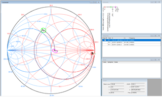
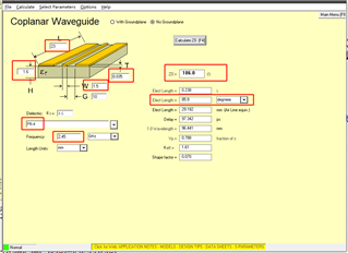
But I made a calculation using the software AppCAD, and found out if I layout the antenna following above paramters(FR-4, 1.6mm thickness, 1.5mm antenna width and 1oz copper), the antenna impedance will be 186ohm. (Below picture)

In another document nRF52840_PS_v1.1, chapter7.3.13, it says the antenna needs to be 50ohm.

I'd like to follow the nwp_008 and it seems making sense to me, but just need to double confirm if I did something wrong above.

Thanks,

Vincent

Parents
  • Hi Vincent,


    This is a calculator for a coplanar waveguide (which is a transmission line), not a monopole antenna. The impedance you are calculating is the characteristic impedance of the line, not the antenna load impedance which the nRF52840 PS describes.

    Although not accurate, you could probably get a ballpark impedance model with this. Assume an open and capacitive load at the end of the line, then add your 200 ohm transmission line (quarter wave trasformer), you will end up somewhere near the constant reactance = 1 circle. The load cap will then bring you to 50 Ohm:


    Anyway you are not supposed to worry about calculating or simulating this when following the whitepaper, it will work just fine without, as long as you follow the instructions.


    Best regards,

    Andreas

Reply
  • Hi Vincent,


    This is a calculator for a coplanar waveguide (which is a transmission line), not a monopole antenna. The impedance you are calculating is the characteristic impedance of the line, not the antenna load impedance which the nRF52840 PS describes.

    Although not accurate, you could probably get a ballpark impedance model with this. Assume an open and capacitive load at the end of the line, then add your 200 ohm transmission line (quarter wave trasformer), you will end up somewhere near the constant reactance = 1 circle. The load cap will then bring you to 50 Ohm:


    Anyway you are not supposed to worry about calculating or simulating this when following the whitepaper, it will work just fine without, as long as you follow the instructions.


    Best regards,

    Andreas

Children
Related