This post is older than 2 years and might not be relevant anymore
More Info: Consider searching for newer posts

nRF52840 Dongle matching network for ext. Antenna

Hi,

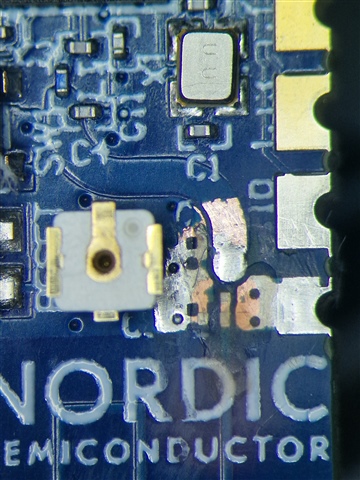
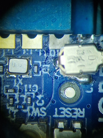
I'm about to develop a custom board with nRF52840 IC. For a first test I need an external antenna. I modified a dongle for a first proof of concept. I removed the antenna trace and soldered SMA connector on it. On the bottom side i connected the connector to the ground plane.

If I understand it correctly, I have to remove C4 and C26 for an eternal antenna design. On the development board, the C3 is 0.8pF and on the dongle it's 1pF. I think that would be ok for the first test.

Can somebody confirm, that the C4 and C26 have to be removed from the dongle, if I want to test it with external SMA connector?

Parents Reply
  • if I would do it again I would just solder a  pig tail SMA with thin cable and not use an UF.L port directly on the pcb.

    Cable core to the thick "snaky trace" and disconnet the existing thin trace to the PCB antenna. Shield can go to the pad right next to it over the big "C" letter and act as a strain relief maybe.

    I used a glassfiber scraper pen to remove the solder mask layer. But anything can be used to sand this down.

Children
No Data
Related