Hi,
I am trying to use SPIM3 to drive LCD(ili9486), but I have encountered some problems, hoping to give me a solution.
I have 2 questions:
1. spi_config.dcx_pin
How to set this pin?I init this pin with NRF_GPIO_PIN_MAP(1,8),but it did't work,I need setup to NRFX_SPIM_PIN_NOT_USED and pull up or pull down this pin in manual.It very weird!
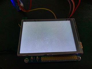
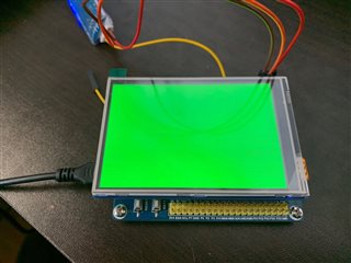
2.LCD_SetPointlColor not work, but LCD_Clear work well
I don't know why this happen,but it was real,I can clear LCD with LCD_Clear function to any color, but I can't draw any point wiht LCD_SetPointColor funciton.It was my funciton write wrong?
Here is my code:
#include "ili9486.h"

#include "nrfx_spim.h"
#include "nrf_delay.h"
#include "lvgl/lvgl.h"

LCD_DIS sLCD_DIS;

static const nrfx_spim_t spi = NRFX_SPIM_INSTANCE(SPI_INSTANCE);  /**< SPI instance. */
static volatile bool spi_xfer_done;  /**< Flag used to indicate that SPI instance completed the transfer. */

void spim_event_handler(nrfx_spim_evt_t const * p_event,void * p_context)
{
  spi_xfer_done = true;
}

static lcd_init_cmd_t ili9486_init_cmds[]={
	{0x01, {0x00}, 0x80},
	{0x28, {0x00}, 0x80},
	{0xF9, {0x00, 0x08}, 2},
	{0xC0, {0x19, 0x1A}, 2},
	{0xC1, {0x45, 0x00}, 2},
	{0xC2, {0x33}, 1},
	{0xC5, {0x00, 0x28}, 2},
	{0xB1, {0xA0, 0x11}, 2},
	{0xB4, {0x02}, 1},
	{0xB6, {0x00, 0x42, 0x3B}, 3},
	{0xB7, {0x07}, 1},
	{0xE0, {0x1F, 0x25, 0x22, 0x0B, 0x06, 0x0A, 0x4E, 0xC6, 0x39, 0x00, 0x00, 0x00, 0x00, 0x00, 0x00}, 15},
	{0xE1, {0x1F, 0x3F, 0x3F, 0x0F, 0x1F, 0x0F, 0x46, 0x49, 0x31, 0x05, 0x09, 0x03, 0x1C, 0x1A, 0x00}, 15},
	{0xF1, {0x36, 0x04, 0x00, 0x3C, 0x0F, 0x0F, 0xA4, 0x02}, 8},
	{0xF2, {0x18, 0xA3, 0x12, 0x02, 0x32, 0x12, 0xFF, 0x32, 0x00}, 9},
	{0xF4, {0x40, 0x00, 0x08, 0x91, 0x04}, 5},
	{0xF8, {0x21, 0x04}, 2},
	{0x3A, {0x55}, 1},
//	{0x11, {0x00}, 0x80},
//	{0x29, {0x00}, 0x80},
	{0x00, {0x00}, 0xFF}
};
static void LCD_Reset(void)
{
    LCD_RST_HIGH;
    nrf_delay_ms(500);
    LCD_RST_LOW;
    nrf_delay_ms(500);
    LCD_RST_HIGH;
    nrf_delay_ms(500);
}

static void LCD_SetBackLight(void)
{
	LCD_BL_HIGH;
}

void LCD_WriteCommand(unsigned char cmd)
{
	nrf_gpio_pin_clear(DC); /* question 1 */
	spi_xfer_done = false;

	nrfx_spim_xfer_desc_t xfer_desc = NRFX_SPIM_XFER_TX(&cmd, 1);
  APP_ERROR_CHECK(nrfx_spim_xfer_dcx(&spi, &xfer_desc, 0,1));
  while(spi_xfer_done == false)
  {

	}
}

void LCD_WriteData(uint8_t *data, int len)
{
	nrf_gpio_pin_set(DC); /* question 1 */
	spi_xfer_done = false;
	if (len == 0) return;

	nrfx_spim_xfer_desc_t xfer_desc = NRFX_SPIM_XFER_TX(data, len);
	APP_ERROR_CHECK(nrfx_spim_xfer_dcx(&spi, &xfer_desc, 0, 0));
	while(spi_xfer_done == false)
	{

	}
}

/*******************************************************************************
function:	Set the display scan and color transfer modes
parameter:
	Scan_dir   :   Scan direction
	Colorchose :   RGB or GBR color format
********************************************************************************/
void LCD_SetGramScanWay(LCD_SCAN_DIR Scan_dir)
{
	uint16_t MemoryAccessReg_Data = 0;
	uint16_t DisFunReg_Data = 0;
	uint8_t dataTemp[2];

	switch (Scan_dir) {
	case L2R_U2D:
			MemoryAccessReg_Data = 0x08;
			DisFunReg_Data = 0x22;
			break;
	case L2R_D2U:
			MemoryAccessReg_Data = 0x08;
			DisFunReg_Data = 0x62;
			break;
	case R2L_U2D:
			MemoryAccessReg_Data = 0x08;
			DisFunReg_Data = 0x02;
			break;
	case R2L_D2U:
			MemoryAccessReg_Data = 0x08;
			DisFunReg_Data = 0x42;
			break;
	case U2D_L2R:
			MemoryAccessReg_Data = 0x28;
			DisFunReg_Data = 0x22;
			break;
	case U2D_R2L:
			MemoryAccessReg_Data = 0x28;
			DisFunReg_Data = 0x02;
			break;
	case D2U_L2R:
			MemoryAccessReg_Data = 0x28;
			DisFunReg_Data = 0x62;
			break;
	case D2U_R2L:
			MemoryAccessReg_Data = 0x28;
			DisFunReg_Data = 0x42;
			break;
	}

	sLCD_DIS.dirction = Scan_dir;

	if(Scan_dir == L2R_U2D || Scan_dir == L2R_D2U || Scan_dir == R2L_U2D || Scan_dir == R2L_D2U) {
			sLCD_DIS.width	= LCD_HEIGHT ;
			sLCD_DIS.height = LCD_WIDTH ;
	} else {
			sLCD_DIS.width	= LCD_WIDTH ;
			sLCD_DIS.height = LCD_HEIGHT ;
	}
	LCD_WriteCommand(0xB6);
	dataTemp[0] = 0x00;
	dataTemp[1] = DisFunReg_Data;
	LCD_WriteData(dataTemp, 2);

	LCD_WriteCommand(0x36);
	dataTemp[0] = MemoryAccessReg_Data;
	LCD_WriteData(dataTemp, 1);
}

void LCD_Init(LCD_SCAN_DIR LCD_ScanDir)
{
	int cmd=0;
	nrf_gpio_cfg_output(RST);
	nrf_gpio_cfg_output(BL);

	nrfx_spim_config_t spi_config = NRFX_SPIM_DEFAULT_CONFIG;
	spi_config.frequency = NRF_SPIM_FREQ_32M;
	spi_config.mode     = NRF_SPIM_MODE_3;
	spi_config.bit_order = SPIM_CONFIG_ORDER_MsbFirst;
	spi_config.ss_pin   = CS_PIN;
	spi_config.miso_pin = NRFX_SPIM_PIN_NOT_USED;
	spi_config.mosi_pin = MOSI_PIN;
	spi_config.sck_pin  = SCK_PIN;
	spi_config.dcx_pin  = NRFX_SPIM_PIN_NOT_USED;  /* question 1 */
	spi_config.use_hw_ss = true;
	spi_config.ss_active_high = false;
//	spi_config.ss_duration = 8;

	APP_ERROR_CHECK(nrfx_spim_init(&spi, &spi_config, spim_event_handler, NULL));

	nrf_gpio_cfg(
				SCK_PIN,
				NRF_GPIO_PIN_DIR_OUTPUT,
				NRF_GPIO_PIN_INPUT_DISCONNECT,
				NRF_GPIO_PIN_NOPULL,
				NRF_GPIO_PIN_H0H1,
				NRF_GPIO_PIN_NOSENSE);

	nrf_gpio_cfg(
				MOSI_PIN,
				NRF_GPIO_PIN_DIR_OUTPUT,
				NRF_GPIO_PIN_INPUT_DISCONNECT,
				NRF_GPIO_PIN_NOPULL,
				NRF_GPIO_PIN_H0H1,
				NRF_GPIO_PIN_NOSENSE);

	nrf_gpio_cfg(
				DC,
				NRF_GPIO_PIN_DIR_OUTPUT,
				NRF_GPIO_PIN_INPUT_DISCONNECT,
				NRF_GPIO_PIN_NOPULL,
				NRF_GPIO_PIN_H0H1,
				NRF_GPIO_PIN_NOSENSE);

	nrf_gpio_cfg(
				CS_PIN,
				NRF_GPIO_PIN_DIR_OUTPUT,
				NRF_GPIO_PIN_INPUT_DISCONNECT,
				NRF_GPIO_PIN_NOPULL,
				NRF_GPIO_PIN_H0H1,
				NRF_GPIO_PIN_NOSENSE);

	LCD_Reset();
	LCD_SetBackLight();
	nrf_delay_ms(200);

	while(ili9486_init_cmds[cmd].databytes != 0xff) {
		LCD_WriteCommand(ili9486_init_cmds[cmd].cmd);

		LCD_WriteData(ili9486_init_cmds[cmd].data, ili9486_init_cmds[cmd].databytes & 0x1F);
		if(ili9486_init_cmds[cmd].databytes & 0x80)
		{
			nrf_delay_ms(100);
		}
		cmd++;
	}

	LCD_SetGramScanWay(LCD_ScanDir);
	nrf_delay_ms(200);
	LCD_WriteCommand(0x11);
	nrf_delay_ms(120);
	LCD_WriteCommand(0x29);
}

/********************************************************************************
function:	Sets the start position and size of the display area
parameter:
	Xstart 	:   X direction Start coordinates
	Ystart  :   Y direction Start coordinates
	Xend    :   X direction end coordinates
	Yend    :   Y direction end coordinates
********************************************************************************/
void LCD_SetWindow(uint16_t Xstart, uint16_t Ystart,	uint16_t Xend, uint16_t Yend)
{
	uint8_t dataTemp[4];

	LCD_WriteCommand(0x2A);
	dataTemp[0] = (uint8_t)(Xstart >> 8);
	dataTemp[1] = (uint8_t)(Xstart & 0xff);
	dataTemp[2] = (uint8_t)((Xend - 1) >> 8);
	dataTemp[3] = (uint8_t)((Xend - 1) & 0xff);
	LCD_WriteData(dataTemp, 4);

	LCD_WriteCommand(0x2B);
	dataTemp[0] = (uint8_t)(Ystart >> 8);
	dataTemp[1] = (uint8_t)(Ystart & 0xff);
	dataTemp[2] = (uint8_t)((Yend - 1) >> 8);
	dataTemp[3] = (uint8_t)((Yend - 1) & 0xff);
	LCD_WriteData(dataTemp, 4);

	LCD_WriteCommand(0x2C);
}

/********************************************************************************
function:	Set the display point (Xpoint, Ypoint)
parameter:
	xStart :   X direction Start coordinates
	xEnd   :   X direction end coordinates
********************************************************************************/
void LCD_SetCursor(uint16_t Xpoint, uint16_t Ypoint)
{
	uint8_t data=0;
	LCD_WriteCommand(0x2a);

	data = (Xpoint&0xff00)>>8;
	LCD_WriteData(&data,1);

	data = Xpoint&0x00ff;
	LCD_WriteData(&data,1);

	LCD_WriteCommand(0x2b);

	data = (Ypoint&0xff00)>>8;
	LCD_WriteData(&data,1);

	data = Ypoint&0x00ff;
	LCD_WriteData(&data,1);

	LCD_WriteCommand(0x2c);
}

 /* question 2 */
void LCD_SetPointColor( uint16_t Xpoint, uint16_t Ypoint, uint16_t Color)
{
	if ((Xpoint <= sLCD_DIS.width) && (Ypoint <= sLCD_DIS.height))
	{
		uint8_t dataTemp[2] = {Color >> 8, Color & 0xFF};
		LCD_SetCursor(Xpoint, Ypoint);
		LCD_WriteData(&dataTemp[0], 2);
	}
}

/********************************************************************************
function:
			Clear screen
********************************************************************************/
void LCD_Clear(uint16_t  Color)
{
	printf("clear\r\n");
	uint8_t col[2]={Color >> 8, Color & 0xff};
	LCD_SetWindow(0, 0, (sLCD_DIS.width-1), (sLCD_DIS.height-1));

	uint8_t data_tmp[ LCD_WIDTH * 2] = { 0 };
	for(uint32_t i = 0; i < LCD_WIDTH * 1; i++)
	{
		data_tmp[2 * i] = col[0];
		data_tmp[2 * i + 1] = col[1];
	}

	for(uint32_t i = 0; i < LCD_HEIGHT; i++)
	{
		LCD_WriteData(&data_tmp[0], LCD_WIDTH*2);
	}
}

void LCD_flush(int32_t x1, int32_t y1, int32_t x2, int32_t y2, const lv_color_t * color_map)
{
	uint32_t size = (x2 - x1 + 1) * (y2 - y1 + 1);
	uint8_t *color_u8 = (uint8_t *)color_map;

	uint8_t color_tmp;


	for(uint32_t i = 0; i < size * 2; i += 2) {

		color_tmp = color_u8[i + 0];
		color_u8[i + 0] = ~color_u8[i + 1];//0xaa;//
		color_u8[i + 1] = ~color_tmp;//0xaa;//

//		color_tmp = color_u8[i + 0];
//		color_u8[i + 0] = color_u8[i + 1];//0xaa;//
//		color_u8[i + 1] = color_tmp;//0xaa;//

	}

	LCD_SetWindow(x1,y1,x2,y2);
	LCD_WriteData(color_u8, size*2);
}
LCD_Clear
LCD_SetPointColor