This post is older than 2 years and might not be relevant anymore
More Info: Consider searching for newer posts

Countermeasures for shortening STOP bit in UART transmission processing

Hello Nordic Support!
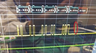
The stop bit of the last character is short in the Uart output part, and the other MPUy cannot receive the character.
How do I fix it until I send the STOP bit completely?
The waveform and the transmission program are described below.
void aUartInterface_SendData(uint8_t *data, uint16_t len)
{
    uint32_t timeout;
    uint32_t start_tick;
    uint32_t current_tick;
    uint8_t sleep = 0;
   
    if(len == 0)
        return;
   
    timeout = TIMEOUT_TICKS*len;
    start_tick = cnt_get();
   
    // check sleep or not
    if(mUartProcessing == 0)
    {
        uart_wakeup();
        sleep = 1;
    }
   
    NRF_GPIO->OUTSET = ((uint32_t)1 << PIN_UART_SENDING);
   
    NRF_UART0->TASKS_STARTTX = 1;
    for(uint16_t i=0; i<len; i++)
    {
        NRF_UART0->TXD = data[i];
        while(NRF_UART0->EVENTS_TXDRDY==0)
        {
            //
            current_tick = cnt_get();
            if( cnt_diff_compute(current_tick, start_tick) > timeout)
            {
                NRF_UART0->EVENTS_TXDRDY = 0;
                NRF_UART0->TASKS_STOPTX = 1;
                NRF_GPIO->OUTCLR = ((uint32_t)1 << PIN_UART_SENDING);
                return;
            }
        }
        NRF_UART0->EVENTS_TXDRDY = 0;
    }
    NRF_UART0->TASKS_STOPTX = 1;
   
    NRF_GPIO->OUTCLR = ((uint32_t)1 << PIN_UART_SENDING);
   
    if(sleep)
        uart_sleep();
}
let me know.
Best Regards
Hirotoshi NAGAO
CHINO Corporation
Parents
  • Hi,

    What is PIN_UART_SENDING? Is this the TX pin of the UART peripheral, or is it a separate GPIO?

    Can you post the entire application so we can see the UART config and how you call this function?

    Best regards,
    Jørgen

  • Hi,
    The nRF52 UART cannot be used to return from an interrupt from Sleep(WFI,etc).
    Between the controller MPU and the nRF52, in addition to the UART, a GPIO that can be used as an interrupt is input and one for output is assigned as a Strobe signal for UART transmission. PUN_UART_SENDING means bit 29 of GPIO.
    A part of the uart initialization and configuration excerpt is described below.

    Best Regard


    // 構造体・enum定義.

    enum
    {
        RCV_STATUS_WAIT_STX = 0,
        RCV_STATUS_WAIT_LENGTH,
        RCV_STATUS_WAIT_DATA,
        RCV_STATUS_WAIT_CHECKSUM,
        RCV_STATUS_WAIT_ETX,
    };

    /***********************************************************************************
    * CONSTANTS
    */

    // 固定値.
    // const型やdefineによる定数.

    #if 0

    #define PIN_UART_RXD 8
    #define PIN_UART_TXD 6
    #define PIN_UART_RTS 0
    #define PIN_UART_CTS 0

    #define PIN_UART_WAKEUP 30
    #define PIN_UART_SENDING 29

    #else

    #define PIN_UART_RXD 31
    #define PIN_UART_TXD 30
    #define PIN_UART_RTS 0
    #define PIN_UART_CTS 0

    #define PIN_UART_WAKEUP 28
    #define PIN_UART_SENDING 29

    #endif

    #define STX 0x02
    #define ETX 0x03


    static void uart_sleep(void)
    {
        NRF_UART0->ENABLE = 0;
       
        NRF_UART0->TASKS_STOPRX = 1;
        NRF_UART0->INTENCLR = (1<<2);   // RX Ready,
       
        NRF_UART0->EVENTS_RXDRDY = 0;
        sd_nvic_ClearPendingIRQ(UART0_IRQn);
       
        NRF_UART0->PSELRXD = 0xFFFFFFFF;
        NRF_UART0->PSELTXD = 0xFFFFFFFF;
       
        // GPIO
        //nrf_gpio_cfg_input(PIN_UART_TXD, NRF_GPIO_PIN_NOPULL);          // 80uA程度, 0出力なし (DK).
        //nrf_gpio_cfg_input(PIN_UART_RXD, NRF_GPIO_PIN_NOPULL);
        //nrf_gpio_cfg_input(PIN_UART_TXD, NRF_GPIO_PIN_PULLDOWN);  // 3uA未満, 0出力あり (DK).
        //nrf_gpio_cfg_input(PIN_UART_RXD, NRF_GPIO_PIN_PULLDOWN);
    //    nrf_gpio_cfg_input(PIN_UART_TXD, NRF_GPIO_PIN_PULLUP);  // 3uA未満, 0出力なし (DK).
        nrf_gpio_cfg_input(PIN_UART_RXD, NRF_GPIO_PIN_PULLUP);
       
        mUartProcessing = 0;
    }

    static void uart_wakeup(void)
    {
        // GPIO
        nrf_gpio_cfg_output(PIN_UART_TXD);
        nrf_gpio_cfg_input(PIN_UART_RXD, NRF_GPIO_PIN_NOPULL);
       
        NRF_UART0->PSELRXD = PIN_UART_RXD;
        NRF_UART0->PSELTXD = PIN_UART_TXD;
       
        NRF_UART0->INTENSET = (1<<2);   // RX Ready,
        NRF_UART0->ENABLE = 4;
       
        NRF_UART0->TASKS_STARTRX = 1;
       
        NRF_UART0->EVENTS_RXDRDY = 0;
        sd_nvic_ClearPendingIRQ(UART0_IRQn);
       
        mUartProcessing = 1;
    }

    void checkGPIO(void)
    {
        if(nrf_gpio_pin_read(PIN_UART_WAKEUP)==0)
        {
           
            NRF_LOG_INFO("Wake up is Low");
           
            // goto sleep
            nrf_gpio_cfg_sense_input(PIN_UART_WAKEUP, NRF_GPIO_PIN_NOPULL, NRF_GPIO_PIN_SENSE_HIGH);
            uart_sleep();
           
            //cnt_stop();   //
        }
        else
        {
            NRF_LOG_INFO("Wake up is High");
           
            // wakeup
            nrf_gpio_cfg_sense_input(PIN_UART_WAKEUP, NRF_GPIO_PIN_NOPULL, NRF_GPIO_PIN_SENSE_LOW);
            uart_wakeup();
           
            cnt_start();
        }
    }

    /***********************************************************************************
    * GLOBAL FUNCTIONS
    */

    // グローバル関数.

    void aUartInterface_Init()
    {
       
        mUartCmdRecv = 0;
        mUartProcessing = 0;
       
        mRecvLen = 0;
        mRecvBufIndx = 0;
       
        // GPIO
        /*
        NRF_GPIO->DIRSET = ((uint32_t)1 << PIN_UART_SENDING);
        NRF_GPIO->DIRCLR = (1 << PIN_UART_WAKEUP);
        */
        nrf_gpio_cfg_output(PIN_UART_SENDING);
        nrf_gpio_cfg_input(PIN_UART_WAKEUP, NRF_GPIO_PIN_NOPULL);
       
        // GPIOTE
        nrf_gpio_cfg_sense_input(PIN_UART_WAKEUP, NRF_GPIO_PIN_NOPULL, NRF_GPIO_PIN_SENSE_HIGH);
        NRF_GPIOTE->INTENSET = GPIOTE_INTENSET_PORT_Msk;
        sd_nvic_SetPriority(GPIOTE_IRQn, APP_IRQ_PRIORITY_LOW);
        sd_nvic_EnableIRQ(GPIOTE_IRQn);
       
        // UART.
        /*
        NRF_GPIO->DIRSET = (1<<PIN_UART_TXD);
        NRF_GPIO->DIRCLR = (1<<PIN_UART_RXD);
        */
        nrf_gpio_cfg_output(PIN_UART_TXD);
        nrf_gpio_cfg_input(PIN_UART_RXD, NRF_GPIO_PIN_NOPULL);
       
        NRF_UART0->PSELRXD = PIN_UART_RXD;
        NRF_UART0->PSELTXD = PIN_UART_TXD;
       
        //NRF_UART0->BAUDRATE = UART_BAUDRATE_BAUDRATE_Baud57600;
        NRF_UART0->BAUDRATE = UART_BAUDRATE_BAUDRATE_Baud9600;
       
        NRF_UART0->INTENSET = (1<<2);   // RX Ready,
       
        NRF_UART0->ENABLE = 4;
       
        sd_nvic_SetPriority(UART0_IRQn, APP_IRQ_PRIORITY_LOW);
        sd_nvic_EnableIRQ(UART0_IRQn);
       
        // timeout
        cnt_init();
       
        // check GPIO
        checkGPIO();
    }

Reply
  • Hi,
    The nRF52 UART cannot be used to return from an interrupt from Sleep(WFI,etc).
    Between the controller MPU and the nRF52, in addition to the UART, a GPIO that can be used as an interrupt is input and one for output is assigned as a Strobe signal for UART transmission. PUN_UART_SENDING means bit 29 of GPIO.
    A part of the uart initialization and configuration excerpt is described below.

    Best Regard


    // 構造体・enum定義.

    enum
    {
        RCV_STATUS_WAIT_STX = 0,
        RCV_STATUS_WAIT_LENGTH,
        RCV_STATUS_WAIT_DATA,
        RCV_STATUS_WAIT_CHECKSUM,
        RCV_STATUS_WAIT_ETX,
    };

    /***********************************************************************************
    * CONSTANTS
    */

    // 固定値.
    // const型やdefineによる定数.

    #if 0

    #define PIN_UART_RXD 8
    #define PIN_UART_TXD 6
    #define PIN_UART_RTS 0
    #define PIN_UART_CTS 0

    #define PIN_UART_WAKEUP 30
    #define PIN_UART_SENDING 29

    #else

    #define PIN_UART_RXD 31
    #define PIN_UART_TXD 30
    #define PIN_UART_RTS 0
    #define PIN_UART_CTS 0

    #define PIN_UART_WAKEUP 28
    #define PIN_UART_SENDING 29

    #endif

    #define STX 0x02
    #define ETX 0x03


    static void uart_sleep(void)
    {
        NRF_UART0->ENABLE = 0;
       
        NRF_UART0->TASKS_STOPRX = 1;
        NRF_UART0->INTENCLR = (1<<2);   // RX Ready,
       
        NRF_UART0->EVENTS_RXDRDY = 0;
        sd_nvic_ClearPendingIRQ(UART0_IRQn);
       
        NRF_UART0->PSELRXD = 0xFFFFFFFF;
        NRF_UART0->PSELTXD = 0xFFFFFFFF;
       
        // GPIO
        //nrf_gpio_cfg_input(PIN_UART_TXD, NRF_GPIO_PIN_NOPULL);          // 80uA程度, 0出力なし (DK).
        //nrf_gpio_cfg_input(PIN_UART_RXD, NRF_GPIO_PIN_NOPULL);
        //nrf_gpio_cfg_input(PIN_UART_TXD, NRF_GPIO_PIN_PULLDOWN);  // 3uA未満, 0出力あり (DK).
        //nrf_gpio_cfg_input(PIN_UART_RXD, NRF_GPIO_PIN_PULLDOWN);
    //    nrf_gpio_cfg_input(PIN_UART_TXD, NRF_GPIO_PIN_PULLUP);  // 3uA未満, 0出力なし (DK).
        nrf_gpio_cfg_input(PIN_UART_RXD, NRF_GPIO_PIN_PULLUP);
       
        mUartProcessing = 0;
    }

    static void uart_wakeup(void)
    {
        // GPIO
        nrf_gpio_cfg_output(PIN_UART_TXD);
        nrf_gpio_cfg_input(PIN_UART_RXD, NRF_GPIO_PIN_NOPULL);
       
        NRF_UART0->PSELRXD = PIN_UART_RXD;
        NRF_UART0->PSELTXD = PIN_UART_TXD;
       
        NRF_UART0->INTENSET = (1<<2);   // RX Ready,
        NRF_UART0->ENABLE = 4;
       
        NRF_UART0->TASKS_STARTRX = 1;
       
        NRF_UART0->EVENTS_RXDRDY = 0;
        sd_nvic_ClearPendingIRQ(UART0_IRQn);
       
        mUartProcessing = 1;
    }

    void checkGPIO(void)
    {
        if(nrf_gpio_pin_read(PIN_UART_WAKEUP)==0)
        {
           
            NRF_LOG_INFO("Wake up is Low");
           
            // goto sleep
            nrf_gpio_cfg_sense_input(PIN_UART_WAKEUP, NRF_GPIO_PIN_NOPULL, NRF_GPIO_PIN_SENSE_HIGH);
            uart_sleep();
           
            //cnt_stop();   //
        }
        else
        {
            NRF_LOG_INFO("Wake up is High");
           
            // wakeup
            nrf_gpio_cfg_sense_input(PIN_UART_WAKEUP, NRF_GPIO_PIN_NOPULL, NRF_GPIO_PIN_SENSE_LOW);
            uart_wakeup();
           
            cnt_start();
        }
    }

    /***********************************************************************************
    * GLOBAL FUNCTIONS
    */

    // グローバル関数.

    void aUartInterface_Init()
    {
       
        mUartCmdRecv = 0;
        mUartProcessing = 0;
       
        mRecvLen = 0;
        mRecvBufIndx = 0;
       
        // GPIO
        /*
        NRF_GPIO->DIRSET = ((uint32_t)1 << PIN_UART_SENDING);
        NRF_GPIO->DIRCLR = (1 << PIN_UART_WAKEUP);
        */
        nrf_gpio_cfg_output(PIN_UART_SENDING);
        nrf_gpio_cfg_input(PIN_UART_WAKEUP, NRF_GPIO_PIN_NOPULL);
       
        // GPIOTE
        nrf_gpio_cfg_sense_input(PIN_UART_WAKEUP, NRF_GPIO_PIN_NOPULL, NRF_GPIO_PIN_SENSE_HIGH);
        NRF_GPIOTE->INTENSET = GPIOTE_INTENSET_PORT_Msk;
        sd_nvic_SetPriority(GPIOTE_IRQn, APP_IRQ_PRIORITY_LOW);
        sd_nvic_EnableIRQ(GPIOTE_IRQn);
       
        // UART.
        /*
        NRF_GPIO->DIRSET = (1<<PIN_UART_TXD);
        NRF_GPIO->DIRCLR = (1<<PIN_UART_RXD);
        */
        nrf_gpio_cfg_output(PIN_UART_TXD);
        nrf_gpio_cfg_input(PIN_UART_RXD, NRF_GPIO_PIN_NOPULL);
       
        NRF_UART0->PSELRXD = PIN_UART_RXD;
        NRF_UART0->PSELTXD = PIN_UART_TXD;
       
        //NRF_UART0->BAUDRATE = UART_BAUDRATE_BAUDRATE_Baud57600;
        NRF_UART0->BAUDRATE = UART_BAUDRATE_BAUDRATE_Baud9600;
       
        NRF_UART0->INTENSET = (1<<2);   // RX Ready,
       
        NRF_UART0->ENABLE = 4;
       
        sd_nvic_SetPriority(UART0_IRQn, APP_IRQ_PRIORITY_LOW);
        sd_nvic_EnableIRQ(UART0_IRQn);
       
        // timeout
        cnt_init();
       
        // check GPIO
        checkGPIO();
    }

Children
No Data
Related