This post is older than 2 years and might not be relevant anymore
More Info: Consider searching for newer posts

General feedback on hardware design and antenna placement

Dear Community,

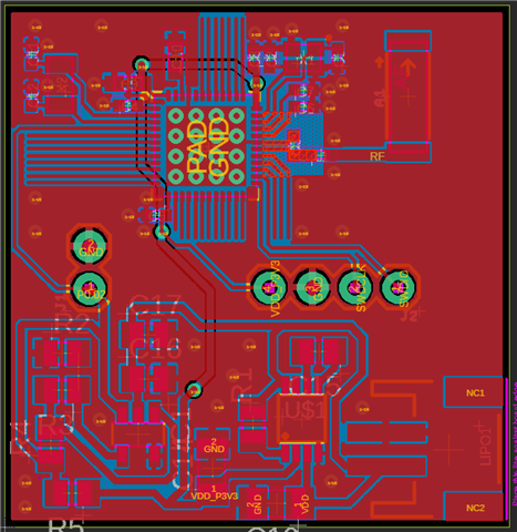
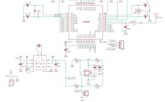
I am working on a project where the idea is to build a board that can measure the resistance over a small biosensor. The biosensor will be connected between GND and P0.02. The theory is to apply a small current over the resistor and then measure the resulting voltage with the ADC. I will use a LiPO battery and, a step down voltage regulator and an operational amplifier. I have used the reference design for the nrf52832 and tried to keep that intact as much as possible.

Any general feedback regarding the design would be very helpful and since this is my first time designing with the nrf52832 I might have done some obvious mistakes. All feedback regarding placement, tracing (ie the VDD_P3V3 going under VDD), noise or ground-loops would be appreciated.

Regarding the antenna and antenna placement I am kinda lost. I read the documentation available here on the forum and decided on a chip antenna that according to the datasheet has an impedance of 50 Ohm. I have attached eagle schematic and board files and images.


 nRF52832_qfaa.brdnRF52832_qfaa.sch

Parents
  • A good start. But you need place the antenna so it's not covered by the ground plane and do ground plane under the antenna either, like this: 

    See if there's a recommended placement and layout in the antenna's datasheet. Very often, they will say something about the distance to ground etc. 

    And no, the antenna will not be 50 ohm. This is rarely the case and depends on the placement, size of the ground plane etc. So you will need tuning components to tune the antenna. A pi-network is good for this, see this whitepaper: https://infocenter.nordicsemi.com/pdf/nwp_017.pdf

    Place this near the antenna, but still on the ground plane. 

    If you have space for it, you can also make a 1/4 wave antenna with a track, about 23 mm long. . This have often better performance than a chip antenna and it's easier to tune. Also in the whitepaper. This can look like this for instance: 

Reply
  • A good start. But you need place the antenna so it's not covered by the ground plane and do ground plane under the antenna either, like this: 

    See if there's a recommended placement and layout in the antenna's datasheet. Very often, they will say something about the distance to ground etc. 

    And no, the antenna will not be 50 ohm. This is rarely the case and depends on the placement, size of the ground plane etc. So you will need tuning components to tune the antenna. A pi-network is good for this, see this whitepaper: https://infocenter.nordicsemi.com/pdf/nwp_017.pdf

    Place this near the antenna, but still on the ground plane. 

    If you have space for it, you can also make a 1/4 wave antenna with a track, about 23 mm long. . This have often better performance than a chip antenna and it's easier to tune. Also in the whitepaper. This can look like this for instance: 

Children
Related