This post is older than 2 years and might not be relevant anymore
More Info: Consider searching for newer posts

M33 core in nRF9160 low power mode - Constant latency mode

Hello, I am working on low power modes of MCU M33 core in nRF9160 SOC.

From the document of nRF9160 product specification v1.0, understood that there are two low power modes for M33 core 

1. System ON Mode

     a. Low power mode - Default mode after reset

     b. Constant Latency mode.

2.System OFF Mode - The device is put into System OFF mode using the REGULATORS register interface.

As you suggested in my previous case Case ID: 246126, In serial Link monitor example code, I found enter_sleep() function which is actually System OFF Mode.

I have changed the enter_Sleep() function to enter into system ON mode instead of System OFF mode as in the example.

Below are my code which I am trying to wake up using GPIO button from system ON mode - low power mode but not successful.

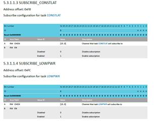
When I checked the TASKS_LOWPWR register in embedded segger studio mode, the value in this register is still 0  though I am writing 1 to this register using nrf_power_task_trigger(NRF_POWER_NS,NRF_POWER_TASK_LOWPWR) API

I have also checked operation of the System ON mode - Constant Latency Mode, TASKS_CONSTLAT register is still 0.

void enter_sleep(void)
{

nrf_gpio_cfg_input(CONFIG_SLM_INTERFACE_PIN,
NRF_GPIO_PIN_PULLUP);
nrf_gpio_cfg_sense_set(CONFIG_SLM_INTERFACE_PIN,
NRF_GPIO_PIN_SENSE_LOW);


lte_lc_power_off();
bsd_shutdown();
nrf_power_task_trigger(NRF_POWER_NS,NRF_POWER_TASK_LOWPWR);

}

Can you guide me how to enable these modes- low power and contant latency mode.

  • Hi,

    In addition to my previous query, Could you also give me information for the following registers

    FOr what these registers about....channel index means any GPIO pins?

    Does it give any signal on selected GPIO if low power mode or constant latency mode is selected?

  • Hi!

    TASKS_CONSTLAT and TASKS_LOWPWR are task registers with write access only, so you can't read from them. If you are able to write to them without receiving an error, then the write was successful. You can read more about task registers: 3.3.5 Tasks.

    The subscribe registers SUBSCRIBE_CONSTLAT and SUBSCRIBE_LOWPWR lets you subscribe to an event, so when the task sees that the event has been triggered, it will trigger the task without using the CPU. The registers mentioned in the SUBSCRIBE registers are the DPPI channels on the nRF9160, there are 16 of them. Here is more information about the subscribe registers: 3.3.7 Publish / Subscribe.

    So if you enable the subscription to a specific DPPI channel, a separate event can publish to that same DPPI channel which will, in turn, trigger the task related to that subscribe register, so either TASKS_CONSTLAT or TASKS_LOWPWR. 

    Best regards,

    Heidi

  • Hi Heidi,

    Thank you for giving me more insight to peripheral task ,events and DPPI concepts.

    Few more queries:

    1. If I write directly to TASKS_CONSTLAT and TASKS_LOWPWR register as in my implementation, will the respective modes are enabled? If yes how to conform whether M33 core is in particular mode and saving power.

    2. What are the current consumption of SoC in these modes( Low power mode and Constant Latency mode).

    3.  Is my implementation correct for low power mode

    void enter_sleep(void)
    {

    nrf_gpio_cfg_input(CONFIG_SLM_INTERFACE_PIN,
    NRF_GPIO_PIN_PULLUP);
    nrf_gpio_cfg_sense_set(CONFIG_SLM_INTERFACE_PIN,
    NRF_GPIO_PIN_SENSE_LOW);


    lte_lc_power_off();
    bsd_shutdown();
    nrf_power_task_trigger(NRF_POWER_NS,NRF_POWER_TASK_LOWPWR);

    }

    4. After going to DPPI peripheral notes, I was thinking to trigger Low power mode/Constant latency mode with timeout event on one of the DPPI channel. Will this work? Can you please point me to some sample code using DPPI peripheral for triggering event which in turn trigger peripheral task.

    --Praveen P

  • Hi!

    1. The modes will be enabled if you write directly to those registers, yes. To confirm, you can measure the current consumption on the chip.

    2. I can't find any specific information about the current consumption for the different modes, so I've put in a request with the developers for any information on this.

    What I can find in the PS is that with MCU on IDLE, modem off and RTC off the typical current consumption down to 1.8 uA.

    The constant latency mode forces the 16 MHz peripheral clock which has a typical current consumption of 867.34 uA, see here.


    3. Your implementation looks correct. However, an easier way to do it is to use Zephyr's own implementations:
    k_cpu_idle() or k_sleep(), which lets the SiP enter system ON IDLE mode (low power mode in System ON)

    4. Yes, you want to set a TIMEOUT event that will publish to a DPPI channel which CONSTLAT or LOWPWR will be subscribing to, so those tasks are triggered? This is possible.

    As for a sample, the closest I could find was the nRF91 nrfx example in zephyr/samples/boards/nrf/nrfx. There is no timer, but it does show how to use the DPPI driver. 

    Best regards,

    Heidi

  • Hi Heidi,

    I am measuring current consumption of nRF9160 in System on mode- idle mode and followed your suggestion to use Zephry implementation k_cpu_idle() .I am seeing current consumption is around 3mA as in attached snapshot.

    In datasheet, mentioned current consumption for system ON mode- Idle mode is around 1.8uA

    Could you please help me how to achieve the current consumption near to the datasheet value.

    I am following the procedure for current measurement given in nRF9160 DK user guide

    Measuring across P24.

    # General config
    CONFIG_ASSERT=y
    CONFIG_LOG=y
    CONFIG_LOG_DEFAULT_LEVEL=3
    CONFIG_STACK_SENTINEL=y
    CONFIG_CP_LOG_LEVEL_INF=y
    
    # Segger RTT
    CONFIG_USE_SEGGER_RTT=y
    CONFIG_RTT_CONSOLE=y
    CONFIG_UART_CONSOLE=n
    CONFIG_LOG_BACKEND_RTT=y
    CONFIG_LOG_BACKEND_UART=n
    
    
    # enable to use thread names
    CONFIG_THREAD_NAME=y
    
    # Network
    CONFIG_NETWORKING=y
    CONFIG_NET_SOCKETS_OFFLOAD=y
    CONFIG_NET_SOCKETS=y
    CONFIG_NET_SOCKETS_POSIX_NAMES=y
    CONFIG_NET_NATIVE=n
    
    # LTE link control
    CONFIG_LTE_LINK_CONTROL=y
    CONFIG_LTE_AUTO_INIT_AND_CONNECT=n
    
    # BSD library
    CONFIG_BSD_LIBRARY=y
    
    # Stacks and heaps
    CONFIG_MAIN_STACK_SIZE=2048
    CONFIG_HEAP_MEM_POOL_SIZE=1024
    
    # Disable native network stack to save some memory
    CONFIG_NET_IPV4=y
    CONFIG_NET_IPV6=n
    CONFIG_NET_UDP=n
    CONFIG_NET_TCP=y
    
    ###gpio related###
    CONFIG_GPIO=y
    
    ###UART CONFIGURATION###
    #Enables serial driver
    CONFIG_SERIAL=y
    
    
    #Needed for enabling ISRs
    CONFIG_UART_INTERRUPT_DRIVEN=y
    
    #UART RAM buffer allocation, see TXD.MAXCNT on nRF9160
    CONFIG_UART_0_NRF_TX_BUFFER_SIZE=1024
    
    ###power management###
    CONFIG_DEVICE_POWER_MANAGEMENT=y
    
    ###RTOS###
    #enables polling
    CONFIG_POLL=y
    
    #PP---???
    CONFIG_DYNAMIC_OBJECTS=y
    
    #enables ring buffer
    CONFIG_RING_BUFFER=y


    My project configuration file prj.conf attached for your reference.

Related