
Hi,
I have got the problem with using BMD-340 demo SPI commuination for many days.
+----------------------------+
| |
| Problem Describtion |
| |
+----------------------------+
1. Developing Tool:
(*) RIGADO BMD-340 Evaluation Kit BMD-340 datasheet
(*) Module based on Nordic nRF52840
-------------------------------------
2. Software: Segger-Embedded-Studio
(*) SEGGER Embedded Studio for ARM 4.30c
(*) nRF5_SDK_16.0.0_98a08e2
(*) Nordic\nRF5_SDK_16.0.0_98a08e2\examples\peripheral
-------------------------------------
3. Present steps
Step 1 - Go folder [D:\User\Nordic\nRF5_SDK_16.0.0_98a08e2\examples\peripheral\nrfx_spim\pca10056\blank\ses].
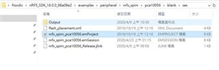
Step 2 - Open [nrfx_spim_pca10056.emProject] by {SEGGER Embedded Studio for ARM 4.30c} .
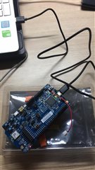
Step 3 - Connect BMD-340 board to PC then turn on the power.
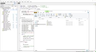
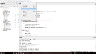
Step 4 - In {SEGGER Embedded Studio for ARM 4.30c} press [Target] -> [Connect J-link].
Step 5 - In {SEGGER Embedded Studio for ARM 4.30c} press [Target] -> [Download nrfx_spim_pca10056].
-------------------------------------
+----------------------------+
| |
| SPI signal output pin |
| |
+----------------------------+
4. Excepted Result
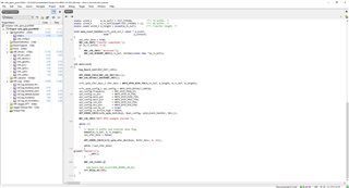
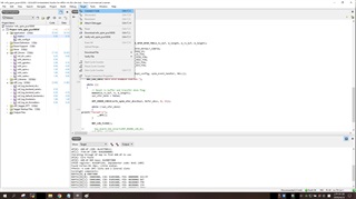
Step 1 - On {SEGGER Embedded Studio for ARM 4.30c} the project [nrfx_spim_pca10056.emProject], see "main.c".
Step 2 - Default SPI specification starting from line 51.
#include "nrfx_spim.h"
#include "app_util_platform.h"
#include "nrf_gpio.h"
#include "nrf_delay.h"
#include "boards.h"
#include "app_error.h"
#include <string.h>
#include "nrf_log.h"
#include "nrf_log_ctrl.h"
#include "nrf_log_default_backends.h"

#define NRFX_SPIM_SCK_PIN  3
#define NRFX_SPIM_MOSI_PIN 4
#define NRFX_SPIM_MISO_PIN 28
#define NRFX_SPIM_SS_PIN   29
#define NRFX_SPIM_DCX_PIN  30

#define SPI_INSTANCE  3                                           /**< SPI instance index. */
static const nrfx_spim_t spi = NRFX_SPIM_INSTANCE(SPI_INSTANCE);  /**< SPI instance. */

static volatile bool spi_xfer_done;  /**< Flag used to indicate that SPI instance completed the transfer. */

#define TEST_STRING "Nordic123456789012345678901234567890"
static uint8_t       m_tx_buf[] = TEST_STRING;           /**< TX buffer. */
static uint8_t       m_rx_buf[sizeof(TEST_STRING) + 1];  /**< RX buffer. */
static const uint8_t m_length = sizeof(m_tx_buf);        /**< Transfer length. */
51 #define NRFX_SPIM_SCK_PIN 3
52 #define NRFX_SPIM_MOSI_PIN 4
53 #define NRFX_SPIM_MISO_PIN 28
54 #define NRFX_SPIM_SS_PIN 29
55 #define NRFX_SPIM_DCX_PIN 30
.
.
.
62 #define TEST_STRING "Nordic123456789012345678901234567890"
Step 3 - so that I get string "Nordic123456789012345678901234567890" at BMD-340 GPIO pin 4 because [#define NRFX_SPIM_MOSI_PIN 4] on line 52.
-------------------------------------
+-----------------------------+
| |
| Logic Analyzer Demo |
| |
+-----------------------------+
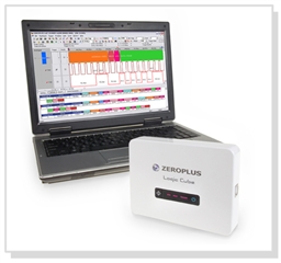
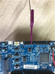
Step 1 - Logic Analyzer connect to BMD-340 GPIOpin4(P0.4 on board) or P0.3
Step 2 - setting analysis rate 100M Hz <-- Must greater than SPI clock rate to get signal
-------------------------------------
+-----------------------+
| |
| Problem |
| |
+-----------------------+
1. no matter what PIN in BMD-340 { P0.3(SCK) P0.4(MOSI) P0.28(MISO) P0.29(SS) P0.30(DCX) } cannot trigger logic analyzer
2. I connect probe of analyzer with PIN VCC (5V0) and logic analyzer was triggered with signal 1.
3. (2) means logic analysis can work and detect signal on port, only SPI definition port has no signal.
+-----------------------+
| |
| NEED HELP |
| |
+-----------------------+
(*) Can anyone explain does any of above steps wrong?
(*) It just a demo SPI transport function, I have tryed other SPI examples like {spi, spi_master_using_nrf_spi_mmgr, spis} in [/peripheral/] but none of them works.
(*) My project is to use [BMD-340] f_open() file, pass value to [FPGA] with SPI and their pin connected together.
+------------------------------------+ +-----------------------+
| | | PC |
| BMD - 340 +==============+ SEGGER |
| | | Embedded Stdio |
+-+------+--------+----------+----+ +-----------------------+
| | | |
|SCK | MOSI | MISO |SS
| | | |
+-+--------+---------+---------+--+
| |
| FPGA |
| |
+------------------------------------+
--------------------------------------------------------
Please info me if there is anything not clear, I am eager to find the solution.

