Hello. I try to configure radio at NRF52811 to prepare antenna switching and get correct I/Q samples from different antennas. I have 2 antennas that are 6 cm apart from one another. They are connected to the chip through RF switch BGS12SN6E6327XTSA1. I have 2 antennas that are 6 cm apart from one another. They are connected to the chip through RF switch BGS12SN6E6327XTSA1. It has a switching time of 0.4 μs and it’s control pin is connected to P0.22. As a basis, I took an example “radio” from SDK.
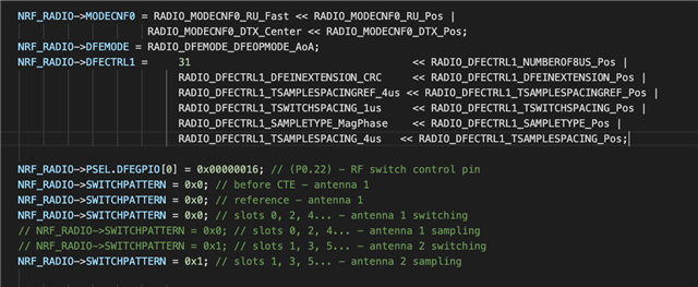
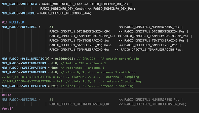
1. In function radio_config() I add some configuration (to the end of function):

2. In main() I add:
NRF_RADIO->PACKETPTR = (uint32_t)&packet;
where packet is an array for handle CTE info.
3. The code for the receiver and transmitter differ only in the call of the corresponding functions of reading or sending packets in the main loop.
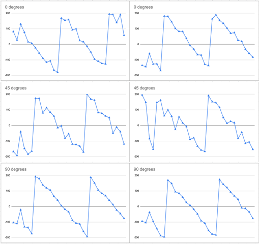
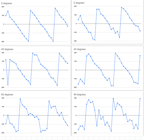
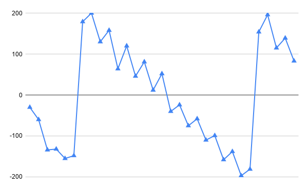
I got I/Q samples at different angles, but for a better understanding of the phase, I set up sampling on MagPhase instead of I/Q. In particular, I assume that 0.2.4 ... samples correspond to the first antenna, and 1.3.5 ... to the second. I assume that when all 3 antennas (2 at the receiver and 1 at the transmitter) are located on the same line (0 degrees), then the phase shift will be maximum, and when an isosceles triangle is obtained from the antennas (90 degrees), then the minimum. However, in practice it turns out almost the same picture, something like this:
I also understand that we work with frames, and not with waves in a straight line, so the question arises, if everything is correctly configured, will the phase shift obtained in this way correspond to the phase shift of the wave. What do I mean: if it were a phase diagram of a real electromagnetic wave with a wavelength of 12 cm, then in this case we would get a phase shift change from 0 degrees (antennas form a hip triangle) to 180 degrees (antennas lay on one line). And what should we get when working with frames?