This post is older than 2 years and might not be relevant anymore
More Info: Consider searching for newer posts

Configure radio at NRF52811 for antenna switching

Hello. I try to configure radio at NRF52811 to prepare antenna switching and get correct I/Q samples from different antennas. I have 2 antennas that are 6 cm apart from one another. They are connected to the chip through RF switch BGS12SN6E6327XTSA1. I have 2 antennas that are 6 cm apart from one another. They are connected to the chip through RF switch BGS12SN6E6327XTSA1. It has a switching time of 0.4 μs and it’s control pin is connected to P0.22. As a basis, I took an example “radio” from SDK.

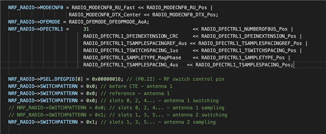
1. In function radio_config() I add some configuration (to the end of function):

2. In main() I add:

NRF_RADIO->PACKETPTR = (uint32_t)&packet;

where packet is an array for handle CTE info.

3. The code for the receiver and transmitter differ only in the call of the corresponding functions of reading or sending packets in the main loop.

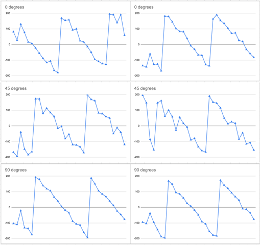
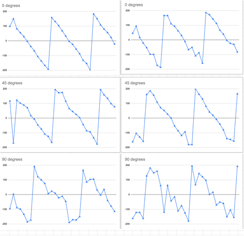
I got I/Q samples at different angles, but for a better understanding of the phase, I set up sampling on MagPhase instead of I/Q. In particular, I assume that 0.2.4 ... samples correspond to the first antenna, and 1.3.5 ... to the second. I assume that when all 3 antennas (2 at the receiver and 1 at the transmitter) are located on the same line (0 degrees), then the phase shift will be maximum, and when an isosceles triangle is obtained from the antennas (90 degrees), then the minimum. However, in practice it turns out almost the same picture, something like this:

I also understand that we work with frames, and not with waves in a straight line, so the question arises, if everything is correctly configured, will the phase shift obtained in this way correspond to the phase shift of the wave. What do I mean: if it were a phase diagram of a real electromagnetic wave with a wavelength of 12 cm, then in this case we would get a phase shift change from 0 degrees (antennas form a hip triangle) to 180 degrees (antennas lay on one line). And what should we get when working with frames?

So my questions:
1. How to configure radio to get samples from both antennas correctly (So that the phase shift somehow correlates with the angle between the antennas)?
2. How is the resulting phase shift related to the angle between the antennas? For electromagnetic waves, I understand the following: https://web.wpi.edu/Pubs/E-project/Available/E-project-101012-211424/unrestricted/DirectionFindingPresentation.pdf
Parents Reply Children
  • PHYEND does seem to be generated in Rx mode. It's just not shown in the nRF52811 product spec. It is shown in the nRF52833 PS. If you use END to disable you might truncate your samples.

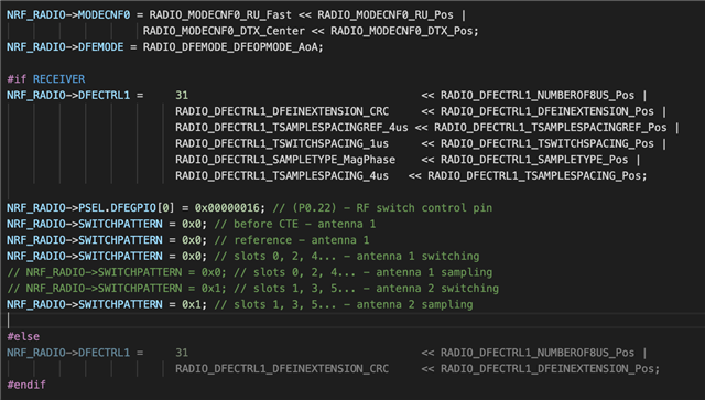
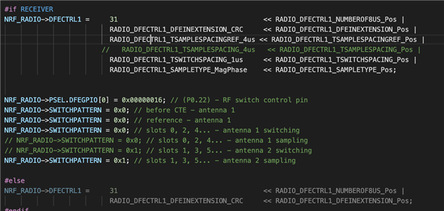
  • Hi. There is full config code:

    #include "radio_config.h"
    #include "nrf_delay.h"
    
    #define RECEIVER    1
    #define TRANSMITTER !RECEIVER
    
    /* These are set to zero as ShockBurst packets don't have corresponding fields. */
    #define PACKET_S1_FIELD_SIZE      (0UL)  /**< Packet S1 field size in bits. */
    #define PACKET_S0_FIELD_SIZE      (0UL)  /**< Packet S0 field size in bits. */
    #define PACKET_LENGTH_FIELD_SIZE  (0UL)  /**< Packet length field size in bits. */
    
    /**
     * @brief Function for swapping/mirroring bits in a byte.
     *
     *@verbatim
     * output_bit_7 = input_bit_0
     * output_bit_6 = input_bit_1
     *           :
     * output_bit_0 = input_bit_7
     *@endverbatim
     *
     * @param[in] inp is the input byte to be swapped.
     *
     * @return
     * Returns the swapped/mirrored input byte.
     */
    static uint32_t swap_bits(uint32_t inp);
    
    /**
     * @brief Function for swapping bits in a 32 bit word for each byte individually.
     *
     * The bits are swapped as follows:
     * @verbatim
     * output[31:24] = input[24:31]
     * output[23:16] = input[16:23]
     * output[15:8]  = input[8:15]
     * output[7:0]   = input[0:7]
     * @endverbatim
     * @param[in] input is the input word to be swapped.
     *
     * @return
     * Returns the swapped input byte.
     */
    static uint32_t bytewise_bitswap(uint32_t inp);
    
    static uint32_t swap_bits(uint32_t inp)
    {
        uint32_t i;
        uint32_t retval = 0;
    
        inp = (inp & 0x000000FFUL);
    
        for (i = 0; i < 8; i++)
        {
            retval |= ((inp >> i) & 0x01) << (7 - i);
        }
    
        return retval;
    }
    
    
    static uint32_t bytewise_bitswap(uint32_t inp)
    {
          return (swap_bits(inp >> 24) << 24)
               | (swap_bits(inp >> 16) << 16)
               | (swap_bits(inp >> 8) << 8)
               | (swap_bits(inp));
    }
    
    
    /**
     * @brief Function for configuring the radio to operate in ShockBurst compatible mode.
     *
     * To configure the application running on nRF24L series devices:
     *
     * @verbatim
     * uint8_t tx_address[5] = { 0xC0, 0x01, 0x23, 0x45, 0x67 };
     * hal_nrf_set_rf_channel(7);
     * hal_nrf_set_address_width(HAL_NRF_AW_5BYTES);
     * hal_nrf_set_address(HAL_NRF_TX, tx_address);
     * hal_nrf_set_address(HAL_NRF_PIPE0, tx_address);
     * hal_nrf_open_pipe(0, false);
     * hal_nrf_set_datarate(HAL_NRF_1MBPS);
     * hal_nrf_set_crc_mode(HAL_NRF_CRC_16BIT);
     * hal_nrf_setup_dynamic_payload(0xFF);
     * hal_nrf_enable_dynamic_payload(false);
     * @endverbatim
     *
     * When transmitting packets with hal_nrf_write_tx_payload(const uint8_t *tx_pload, uint8_t length),
     * match the length with PACKET_STATIC_LENGTH.
     * hal_nrf_write_tx_payload(payload, PACKET_STATIC_LENGTH);
     *
    */
    void radio_configure()
    {
        // Radio config
        NRF_RADIO->TXPOWER   = (RADIO_TXPOWER_TXPOWER_Pos4dBm/*RADIO_TXPOWER_TXPOWER_0dBm*/ << RADIO_TXPOWER_TXPOWER_Pos);
        NRF_RADIO->FREQUENCY = 16UL;
        NRF_RADIO->MODE      = (RADIO_MODE_MODE_Ble_2Mbit/*RADIO_MODE_MODE_Nrf_1Mbit*/ << RADIO_MODE_MODE_Pos);
    
        // Radio address config
        NRF_RADIO->PREFIX0 =
            ((uint32_t)swap_bits(0xC3) << 24) // Prefix byte of address 3 converted to nRF24L series format
          | ((uint32_t)swap_bits(0xC2) << 16) // Prefix byte of address 2 converted to nRF24L series format
          | ((uint32_t)swap_bits(0xC1) << 8)  // Prefix byte of address 1 converted to nRF24L series format
          | ((uint32_t)swap_bits(0xC0) << 0); // Prefix byte of address 0 converted to nRF24L series format
    
        NRF_RADIO->PREFIX1 =
            ((uint32_t)swap_bits(0xC7) << 24) // Prefix byte of address 7 converted to nRF24L series format
          | ((uint32_t)swap_bits(0xC6) << 16) // Prefix byte of address 6 converted to nRF24L series format
          | ((uint32_t)swap_bits(0xC4) << 0); // Prefix byte of address 4 converted to nRF24L series format
    
        NRF_RADIO->BASE0 = bytewise_bitswap(0x01234567UL);  // Base address for prefix 0 converted to nRF24L series format
        NRF_RADIO->BASE1 = bytewise_bitswap(0x89ABCDEFUL);  // Base address for prefix 1-7 converted to nRF24L series format
    
        NRF_RADIO->TXADDRESS   = 0x00UL;  // Set device address 0 to use when transmitting
        NRF_RADIO->RXADDRESSES = 0x01UL;  // Enable device address 0 to use to select which addresses to receive
    
        // Packet configuration
        NRF_RADIO->PCNF0 = (PACKET_S1_FIELD_SIZE     << RADIO_PCNF0_S1LEN_Pos) |
                           (PACKET_S0_FIELD_SIZE     << RADIO_PCNF0_S0LEN_Pos) |
                           (PACKET_LENGTH_FIELD_SIZE << RADIO_PCNF0_LFLEN_Pos); //lint !e845 "The right argument to operator '|' is certain to be 0"
    
        // Packet configuration
        NRF_RADIO->PCNF1 = (RADIO_PCNF1_WHITEEN_Disabled << RADIO_PCNF1_WHITEEN_Pos) |
                           (RADIO_PCNF1_ENDIAN_Big       << RADIO_PCNF1_ENDIAN_Pos)  |
                           (PACKET_BASE_ADDRESS_LENGTH   << RADIO_PCNF1_BALEN_Pos)   |
                           (PACKET_STATIC_LENGTH         << RADIO_PCNF1_STATLEN_Pos) |
                           (PACKET_PAYLOAD_MAXSIZE       << RADIO_PCNF1_MAXLEN_Pos); //lint !e845 "The right argument to operator '|' is certain to be 0"
    
        // CRC Config
        //NRF_RADIO->CRCCNF = (RADIO_CRCCNF_LEN_Two << RADIO_CRCCNF_LEN_Pos); // Number of checksum bits
        NRF_RADIO->CRCCNF = (RADIO_CRCCNF_LEN_Disabled << RADIO_CRCCNF_LEN_Pos);
        if ((NRF_RADIO->CRCCNF & RADIO_CRCCNF_LEN_Msk) == (RADIO_CRCCNF_LEN_Two << RADIO_CRCCNF_LEN_Pos))
        {
            NRF_RADIO->CRCINIT = 0xFFFFUL;   // Initial value
            NRF_RADIO->CRCPOLY = 0x11021UL;  // CRC poly: x^16 + x^12^x^5 + 1
        }
        else if ((NRF_RADIO->CRCCNF & RADIO_CRCCNF_LEN_Msk) == (RADIO_CRCCNF_LEN_One << RADIO_CRCCNF_LEN_Pos))
        {
            NRF_RADIO->CRCINIT = 0xFFUL;   // Initial value
            NRF_RADIO->CRCPOLY = 0x107UL;  // CRC poly: x^8 + x^2^x^1 + 1
        }
    
        NRF_RADIO->MODECNF0 = RADIO_MODECNF0_RU_Fast << RADIO_MODECNF0_RU_Pos |
                             RADIO_MODECNF0_DTX_Center << RADIO_MODECNF0_DTX_Pos;
        NRF_RADIO->DFEMODE = RADIO_DFEMODE_DFEOPMODE_AoA;
    
        #if RECEIVER
        NRF_RADIO->DFECTRL1 =     31                                    << RADIO_DFECTRL1_NUMBEROF8US_Pos |
                                  RADIO_DFECTRL1_DFEINEXTENSION_CRC     << RADIO_DFECTRL1_DFEINEXTENSION_Pos |
                                  RADIO_DFECTRL1_TSAMPLESPACINGREF_4us << RADIO_DFECTRL1_TSAMPLESPACINGREF_Pos |
                                //   RADIO_DFECTRL1_TSAMPLESPACING_4us   << RADIO_DFECTRL1_TSAMPLESPACING_Pos |
                                  RADIO_DFECTRL1_TSWITCHSPACING_1us     << RADIO_DFECTRL1_TSWITCHSPACING_Pos |
                                  RADIO_DFECTRL1_SAMPLETYPE_MagPhase    << RADIO_DFECTRL1_SAMPLETYPE_Pos;
                                  
        
        NRF_RADIO->PSEL.DFEGPIO[0] = 0x00000016; // (P0.22) - RF switch control pin
        NRF_RADIO->SWITCHPATTERN = 0x0; // before CTE - antenna 1
        NRF_RADIO->SWITCHPATTERN = 0x0; // reference - antenna 1
        NRF_RADIO->SWITCHPATTERN = 0x0; // slots 0, 2, 4... - antenna 1 switching
        // NRF_RADIO->SWITCHPATTERN = 0x0; // slots 0, 2, 4... - antenna 1 sampling
        // NRF_RADIO->SWITCHPATTERN = 0x1; // slots 1, 3, 5... - antenna 2 switching
        NRF_RADIO->SWITCHPATTERN = 0x1; // slots 1, 3, 5... - antenna 2 sampling
    
        #else
        NRF_RADIO->DFECTRL1 =     31                                    << RADIO_DFECTRL1_NUMBEROF8US_Pos |
                                  RADIO_DFECTRL1_DFEINEXTENSION_CRC     << RADIO_DFECTRL1_DFEINEXTENSION_Pos;
        #endif
    
        //NRF_RADIO->CTEINLINECONF = RADIO_CTEINLINECONF_S0MASK_Msk;
    }
    

    main (main parts of it):

    int16_t i_q1[62];
    
    /**@brief Function for initialization oscillators.
     */
    void clock_initialization()
    {
        /* Start 16 MHz crystal oscillator */
        NRF_CLOCK->EVENTS_HFCLKSTARTED = 0;
        NRF_CLOCK->TASKS_HFCLKSTART    = 1;
    
        /* Wait for the external oscillator to start up */
        while (NRF_CLOCK->EVENTS_HFCLKSTARTED == 0)
        {
            // Do nothing.
        }
    
        /* Start low frequency crystal oscillator for app_timer(used by bsp)*/
        NRF_CLOCK->LFCLKSRC            = (CLOCK_LFCLKSRC_SRC_RC << CLOCK_LFCLKSRC_SRC_Pos);
        NRF_CLOCK->EVENTS_LFCLKSTARTED = 0;
        NRF_CLOCK->TASKS_LFCLKSTART    = 1;
    
        while (NRF_CLOCK->EVENTS_LFCLKSTARTED == 0)
        {
            // Do nothing.
        }
    }
    
    /**@brief Function for sending packet.
     */
    uint32_t send_packet(unsigned long freq, uint16_t *i_q)
    {
        // send the packet:
        uint32_t result = 0;
    
        NRF_RADIO->FREQUENCY = freq;
        NRF_RADIO->DFEPACKET.PTR = i_q;
        NRF_RADIO->EVENTS_READY = 0U;
        NRF_RADIO->TASKS_TXEN   = 1;
        int a = 0;
    
        while (NRF_RADIO->EVENTS_READY == 0U) {}
        NRF_RADIO->EVENTS_END  = 0U;
        NRF_RADIO->TASKS_START = 1U;
    
        while (NRF_RADIO->EVENTS_PHYEND == 0U)
        {
            while (NRF_RADIO->EVENTS_END == 0U) {}
        }
    
        NRF_RADIO->EVENTS_DISABLED = 0U;
        NRF_RADIO->EVENTS_PHYEND = 0U;
        // Disable radio
        NRF_RADIO->TASKS_DISABLE = 1U;
        while (NRF_RADIO->EVENTS_DISABLED == 0U) {}
        return result;
    }
    
    /**@brief Function for reading packet.
     */
    uint32_t read_packet(unsigned long freq, uint16_t *i_q)
    {
        uint32_t result = 0;
        int a = 0;
    
        NRF_RADIO->FREQUENCY = freq;
        NRF_RADIO->DFEPACKET.PTR = i_q;
        NRF_RADIO->EVENTS_READY = 0U;
        // Enable radio and wait for ready
        NRF_RADIO->TASKS_RXEN = 1U;
    
        while (NRF_RADIO->EVENTS_READY == 0U) {}
        NRF_RADIO->EVENTS_END = 0U;
        // Start listening and wait for address received event
        NRF_RADIO->TASKS_START = 1U;
        
        // Wait for end of packet or buttons state changed
        while (NRF_RADIO->EVENTS_PHYEND == 0U)
        {
            while (NRF_RADIO->EVENTS_END == 0U) {}
        }
        NRF_RADIO->EVENTS_DISABLED = 0U;
        NRF_RADIO->EVENTS_PHYEND = 0U;
        
        // Disable radio
        NRF_RADIO->TASKS_DISABLE = 1U;
        while (NRF_RADIO->EVENTS_DISABLED == 0U) {}
        return result;
    }
    
    int main(void)
    {
        uint32_t err_code = NRF_SUCCESS;
    
        clock_initialization();
    
        // Set radio configuration parameters
        nrf_gpio_cfg_output(0x00000016); // (P0.22) - RF switch control pin - set as output prior
        radio_configure();
        NRF_RADIO->PACKETPTR = (uint32_t)&packet;
    
        LOG_DBG("Radio example started.\n");
    
        while (true)
        {
            #if RECEIVER
            read_packet(16UL, i_q1);
            print_logs(1, 2, 3);
            #else
            if (packet != 0)
            {
                send_packet(16UL, i_q1); // send at (2416MHz)\
                packet = 0;
            }
            nrf_delay_ms(500);
            packet++;
            #endif
        }
    }

  • What values should I put in DFECTRL2 and DFEPACKET.MAXCNT? 

    Thanks

Related