This post is older than 2 years and might not be relevant anymore
More Info: Consider searching for newer posts

Configure radio at NRF52811 for antenna switching

Hello. I try to configure radio at NRF52811 to prepare antenna switching and get correct I/Q samples from different antennas. I have 2 antennas that are 6 cm apart from one another. They are connected to the chip through RF switch BGS12SN6E6327XTSA1. I have 2 antennas that are 6 cm apart from one another. They are connected to the chip through RF switch BGS12SN6E6327XTSA1. It has a switching time of 0.4 μs and it’s control pin is connected to P0.22. As a basis, I took an example “radio” from SDK.

1. In function radio_config() I add some configuration (to the end of function):

2. In main() I add:

NRF_RADIO->PACKETPTR = (uint32_t)&packet;

where packet is an array for handle CTE info.

3. The code for the receiver and transmitter differ only in the call of the corresponding functions of reading or sending packets in the main loop.

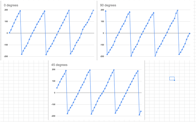
I got I/Q samples at different angles, but for a better understanding of the phase, I set up sampling on MagPhase instead of I/Q. In particular, I assume that 0.2.4 ... samples correspond to the first antenna, and 1.3.5 ... to the second. I assume that when all 3 antennas (2 at the receiver and 1 at the transmitter) are located on the same line (0 degrees), then the phase shift will be maximum, and when an isosceles triangle is obtained from the antennas (90 degrees), then the minimum. However, in practice it turns out almost the same picture, something like this:

I also understand that we work with frames, and not with waves in a straight line, so the question arises, if everything is correctly configured, will the phase shift obtained in this way correspond to the phase shift of the wave. What do I mean: if it were a phase diagram of a real electromagnetic wave with a wavelength of 12 cm, then in this case we would get a phase shift change from 0 degrees (antennas form a hip triangle) to 180 degrees (antennas lay on one line). And what should we get when working with frames?

So my questions:
1. How to configure radio to get samples from both antennas correctly (So that the phase shift somehow correlates with the angle between the antennas)?
2. How is the resulting phase shift related to the angle between the antennas? For electromagnetic waves, I understand the following: https://web.wpi.edu/Pubs/E-project/Available/E-project-101012-211424/unrestricted/DirectionFindingPresentation.pdf
Parents
  • Hi Alex,

    I can't see your configuration, could you reload your first picture?

  • Hi. There is full config code:

    #include "radio_config.h"
    #include "nrf_delay.h"
    
    #define RECEIVER    1
    #define TRANSMITTER !RECEIVER
    
    /* These are set to zero as ShockBurst packets don't have corresponding fields. */
    #define PACKET_S1_FIELD_SIZE      (0UL)  /**< Packet S1 field size in bits. */
    #define PACKET_S0_FIELD_SIZE      (0UL)  /**< Packet S0 field size in bits. */
    #define PACKET_LENGTH_FIELD_SIZE  (0UL)  /**< Packet length field size in bits. */
    
    /**
     * @brief Function for swapping/mirroring bits in a byte.
     *
     *@verbatim
     * output_bit_7 = input_bit_0
     * output_bit_6 = input_bit_1
     *           :
     * output_bit_0 = input_bit_7
     *@endverbatim
     *
     * @param[in] inp is the input byte to be swapped.
     *
     * @return
     * Returns the swapped/mirrored input byte.
     */
    static uint32_t swap_bits(uint32_t inp);
    
    /**
     * @brief Function for swapping bits in a 32 bit word for each byte individually.
     *
     * The bits are swapped as follows:
     * @verbatim
     * output[31:24] = input[24:31]
     * output[23:16] = input[16:23]
     * output[15:8]  = input[8:15]
     * output[7:0]   = input[0:7]
     * @endverbatim
     * @param[in] input is the input word to be swapped.
     *
     * @return
     * Returns the swapped input byte.
     */
    static uint32_t bytewise_bitswap(uint32_t inp);
    
    static uint32_t swap_bits(uint32_t inp)
    {
        uint32_t i;
        uint32_t retval = 0;
    
        inp = (inp & 0x000000FFUL);
    
        for (i = 0; i < 8; i++)
        {
            retval |= ((inp >> i) & 0x01) << (7 - i);
        }
    
        return retval;
    }
    
    
    static uint32_t bytewise_bitswap(uint32_t inp)
    {
          return (swap_bits(inp >> 24) << 24)
               | (swap_bits(inp >> 16) << 16)
               | (swap_bits(inp >> 8) << 8)
               | (swap_bits(inp));
    }
    
    
    /**
     * @brief Function for configuring the radio to operate in ShockBurst compatible mode.
     *
     * To configure the application running on nRF24L series devices:
     *
     * @verbatim
     * uint8_t tx_address[5] = { 0xC0, 0x01, 0x23, 0x45, 0x67 };
     * hal_nrf_set_rf_channel(7);
     * hal_nrf_set_address_width(HAL_NRF_AW_5BYTES);
     * hal_nrf_set_address(HAL_NRF_TX, tx_address);
     * hal_nrf_set_address(HAL_NRF_PIPE0, tx_address);
     * hal_nrf_open_pipe(0, false);
     * hal_nrf_set_datarate(HAL_NRF_1MBPS);
     * hal_nrf_set_crc_mode(HAL_NRF_CRC_16BIT);
     * hal_nrf_setup_dynamic_payload(0xFF);
     * hal_nrf_enable_dynamic_payload(false);
     * @endverbatim
     *
     * When transmitting packets with hal_nrf_write_tx_payload(const uint8_t *tx_pload, uint8_t length),
     * match the length with PACKET_STATIC_LENGTH.
     * hal_nrf_write_tx_payload(payload, PACKET_STATIC_LENGTH);
     *
    */
    void radio_configure()
    {
        // Radio config
        NRF_RADIO->TXPOWER   = (RADIO_TXPOWER_TXPOWER_Pos4dBm/*RADIO_TXPOWER_TXPOWER_0dBm*/ << RADIO_TXPOWER_TXPOWER_Pos);
        NRF_RADIO->FREQUENCY = 16UL;
        NRF_RADIO->MODE      = (RADIO_MODE_MODE_Ble_2Mbit/*RADIO_MODE_MODE_Nrf_1Mbit*/ << RADIO_MODE_MODE_Pos);
    
        // Radio address config
        NRF_RADIO->PREFIX0 =
            ((uint32_t)swap_bits(0xC3) << 24) // Prefix byte of address 3 converted to nRF24L series format
          | ((uint32_t)swap_bits(0xC2) << 16) // Prefix byte of address 2 converted to nRF24L series format
          | ((uint32_t)swap_bits(0xC1) << 8)  // Prefix byte of address 1 converted to nRF24L series format
          | ((uint32_t)swap_bits(0xC0) << 0); // Prefix byte of address 0 converted to nRF24L series format
    
        NRF_RADIO->PREFIX1 =
            ((uint32_t)swap_bits(0xC7) << 24) // Prefix byte of address 7 converted to nRF24L series format
          | ((uint32_t)swap_bits(0xC6) << 16) // Prefix byte of address 6 converted to nRF24L series format
          | ((uint32_t)swap_bits(0xC4) << 0); // Prefix byte of address 4 converted to nRF24L series format
    
        NRF_RADIO->BASE0 = bytewise_bitswap(0x01234567UL);  // Base address for prefix 0 converted to nRF24L series format
        NRF_RADIO->BASE1 = bytewise_bitswap(0x89ABCDEFUL);  // Base address for prefix 1-7 converted to nRF24L series format
    
        NRF_RADIO->TXADDRESS   = 0x00UL;  // Set device address 0 to use when transmitting
        NRF_RADIO->RXADDRESSES = 0x01UL;  // Enable device address 0 to use to select which addresses to receive
    
        // Packet configuration
        NRF_RADIO->PCNF0 = (PACKET_S1_FIELD_SIZE     << RADIO_PCNF0_S1LEN_Pos) |
                           (PACKET_S0_FIELD_SIZE     << RADIO_PCNF0_S0LEN_Pos) |
                           (PACKET_LENGTH_FIELD_SIZE << RADIO_PCNF0_LFLEN_Pos); //lint !e845 "The right argument to operator '|' is certain to be 0"
    
        // Packet configuration
        NRF_RADIO->PCNF1 = (RADIO_PCNF1_WHITEEN_Disabled << RADIO_PCNF1_WHITEEN_Pos) |
                           (RADIO_PCNF1_ENDIAN_Big       << RADIO_PCNF1_ENDIAN_Pos)  |
                           (PACKET_BASE_ADDRESS_LENGTH   << RADIO_PCNF1_BALEN_Pos)   |
                           (PACKET_STATIC_LENGTH         << RADIO_PCNF1_STATLEN_Pos) |
                           (PACKET_PAYLOAD_MAXSIZE       << RADIO_PCNF1_MAXLEN_Pos); //lint !e845 "The right argument to operator '|' is certain to be 0"
    
        // CRC Config
        //NRF_RADIO->CRCCNF = (RADIO_CRCCNF_LEN_Two << RADIO_CRCCNF_LEN_Pos); // Number of checksum bits
        NRF_RADIO->CRCCNF = (RADIO_CRCCNF_LEN_Disabled << RADIO_CRCCNF_LEN_Pos);
        if ((NRF_RADIO->CRCCNF & RADIO_CRCCNF_LEN_Msk) == (RADIO_CRCCNF_LEN_Two << RADIO_CRCCNF_LEN_Pos))
        {
            NRF_RADIO->CRCINIT = 0xFFFFUL;   // Initial value
            NRF_RADIO->CRCPOLY = 0x11021UL;  // CRC poly: x^16 + x^12^x^5 + 1
        }
        else if ((NRF_RADIO->CRCCNF & RADIO_CRCCNF_LEN_Msk) == (RADIO_CRCCNF_LEN_One << RADIO_CRCCNF_LEN_Pos))
        {
            NRF_RADIO->CRCINIT = 0xFFUL;   // Initial value
            NRF_RADIO->CRCPOLY = 0x107UL;  // CRC poly: x^8 + x^2^x^1 + 1
        }
    
        NRF_RADIO->MODECNF0 = RADIO_MODECNF0_RU_Fast << RADIO_MODECNF0_RU_Pos |
                             RADIO_MODECNF0_DTX_Center << RADIO_MODECNF0_DTX_Pos;
        NRF_RADIO->DFEMODE = RADIO_DFEMODE_DFEOPMODE_AoA;
    
        #if RECEIVER
        NRF_RADIO->DFECTRL1 =     31                                    << RADIO_DFECTRL1_NUMBEROF8US_Pos |
                                  RADIO_DFECTRL1_DFEINEXTENSION_CRC     << RADIO_DFECTRL1_DFEINEXTENSION_Pos |
                                  RADIO_DFECTRL1_TSAMPLESPACINGREF_4us << RADIO_DFECTRL1_TSAMPLESPACINGREF_Pos |
                                //   RADIO_DFECTRL1_TSAMPLESPACING_4us   << RADIO_DFECTRL1_TSAMPLESPACING_Pos |
                                  RADIO_DFECTRL1_TSWITCHSPACING_1us     << RADIO_DFECTRL1_TSWITCHSPACING_Pos |
                                  RADIO_DFECTRL1_SAMPLETYPE_MagPhase    << RADIO_DFECTRL1_SAMPLETYPE_Pos;
                                  
        
        NRF_RADIO->PSEL.DFEGPIO[0] = 0x00000016; // (P0.22) - RF switch control pin
        NRF_RADIO->SWITCHPATTERN = 0x0; // before CTE - antenna 1
        NRF_RADIO->SWITCHPATTERN = 0x0; // reference - antenna 1
        NRF_RADIO->SWITCHPATTERN = 0x0; // slots 0, 2, 4... - antenna 1 switching
        // NRF_RADIO->SWITCHPATTERN = 0x0; // slots 0, 2, 4... - antenna 1 sampling
        // NRF_RADIO->SWITCHPATTERN = 0x1; // slots 1, 3, 5... - antenna 2 switching
        NRF_RADIO->SWITCHPATTERN = 0x1; // slots 1, 3, 5... - antenna 2 sampling
    
        #else
        NRF_RADIO->DFECTRL1 =     31                                    << RADIO_DFECTRL1_NUMBEROF8US_Pos |
                                  RADIO_DFECTRL1_DFEINEXTENSION_CRC     << RADIO_DFECTRL1_DFEINEXTENSION_Pos;
        #endif
    
        //NRF_RADIO->CTEINLINECONF = RADIO_CTEINLINECONF_S0MASK_Msk;
    }
    

    main (main parts of it):

    int16_t i_q1[62];
    
    /**@brief Function for initialization oscillators.
     */
    void clock_initialization()
    {
        /* Start 16 MHz crystal oscillator */
        NRF_CLOCK->EVENTS_HFCLKSTARTED = 0;
        NRF_CLOCK->TASKS_HFCLKSTART    = 1;
    
        /* Wait for the external oscillator to start up */
        while (NRF_CLOCK->EVENTS_HFCLKSTARTED == 0)
        {
            // Do nothing.
        }
    
        /* Start low frequency crystal oscillator for app_timer(used by bsp)*/
        NRF_CLOCK->LFCLKSRC            = (CLOCK_LFCLKSRC_SRC_RC << CLOCK_LFCLKSRC_SRC_Pos);
        NRF_CLOCK->EVENTS_LFCLKSTARTED = 0;
        NRF_CLOCK->TASKS_LFCLKSTART    = 1;
    
        while (NRF_CLOCK->EVENTS_LFCLKSTARTED == 0)
        {
            // Do nothing.
        }
    }
    
    /**@brief Function for sending packet.
     */
    uint32_t send_packet(unsigned long freq, uint16_t *i_q)
    {
        // send the packet:
        uint32_t result = 0;
    
        NRF_RADIO->FREQUENCY = freq;
        NRF_RADIO->DFEPACKET.PTR = i_q;
        NRF_RADIO->EVENTS_READY = 0U;
        NRF_RADIO->TASKS_TXEN   = 1;
        int a = 0;
    
        while (NRF_RADIO->EVENTS_READY == 0U) {}
        NRF_RADIO->EVENTS_END  = 0U;
        NRF_RADIO->TASKS_START = 1U;
    
        while (NRF_RADIO->EVENTS_PHYEND == 0U)
        {
            while (NRF_RADIO->EVENTS_END == 0U) {}
        }
    
        NRF_RADIO->EVENTS_DISABLED = 0U;
        NRF_RADIO->EVENTS_PHYEND = 0U;
        // Disable radio
        NRF_RADIO->TASKS_DISABLE = 1U;
        while (NRF_RADIO->EVENTS_DISABLED == 0U) {}
        return result;
    }
    
    /**@brief Function for reading packet.
     */
    uint32_t read_packet(unsigned long freq, uint16_t *i_q)
    {
        uint32_t result = 0;
        int a = 0;
    
        NRF_RADIO->FREQUENCY = freq;
        NRF_RADIO->DFEPACKET.PTR = i_q;
        NRF_RADIO->EVENTS_READY = 0U;
        // Enable radio and wait for ready
        NRF_RADIO->TASKS_RXEN = 1U;
    
        while (NRF_RADIO->EVENTS_READY == 0U) {}
        NRF_RADIO->EVENTS_END = 0U;
        // Start listening and wait for address received event
        NRF_RADIO->TASKS_START = 1U;
        
        // Wait for end of packet or buttons state changed
        while (NRF_RADIO->EVENTS_PHYEND == 0U)
        {
            while (NRF_RADIO->EVENTS_END == 0U) {}
        }
        NRF_RADIO->EVENTS_DISABLED = 0U;
        NRF_RADIO->EVENTS_PHYEND = 0U;
        
        // Disable radio
        NRF_RADIO->TASKS_DISABLE = 1U;
        while (NRF_RADIO->EVENTS_DISABLED == 0U) {}
        return result;
    }
    
    int main(void)
    {
        uint32_t err_code = NRF_SUCCESS;
    
        clock_initialization();
    
        // Set radio configuration parameters
        nrf_gpio_cfg_output(0x00000016); // (P0.22) - RF switch control pin - set as output prior
        radio_configure();
        NRF_RADIO->PACKETPTR = (uint32_t)&packet;
    
        LOG_DBG("Radio example started.\n");
    
        while (true)
        {
            #if RECEIVER
            read_packet(16UL, i_q1);
            print_logs(1, 2, 3);
            #else
            if (packet != 0)
            {
                send_packet(16UL, i_q1); // send at (2416MHz)\
                packet = 0;
            }
            nrf_delay_ms(500);
            packet++;
            #endif
        }
    }

  • Hi, yes, I'm tried an equal number for TSWITCHSPACING and TSAMPLESPACING. But in this case no packets at all was received.

  • What values should I put in DFECTRL2 and DFEPACKET.MAXCNT? 

    Thanks

  • Hi,

    1) your i_q array is too small - for 31*8 usec, even with 4-usec sampling, you will get (2+31*2)*4=256 bytes. Also it's safer to set DFEPACKET.MAXCNT to the maximum number of samples your array can hold.

    2) you need to configure PACKETPTR and allocate a memory for it, even if you don't expect any bytes to exchange. I would create some small payload with CRC, thus you can check at receiver side that packet is received correctly and you can trust AoA samples. (there is another point - you're configuring DFE after CRC event, how it will work when CRC is disabled?)

    3) leave TSAMPLESPACING with some documented value, nobody can tell what's happen when it's zeroed.

    4) I would not rely on PHYEND at receiver side as it's not documented. For now, just add nrf_delay_us() after getting END event to wait while all samples are received.

  • So, I did:

    1. larger array (2048 val.)

    2. set DFEPACKET.MAXCNT = 2048

    3. TSAMPLESPACING == TSAMPLESPACINGREF = 125ns

    4 . different. setting for receiver and transmitter

    5 . DFECTRL2 = 0 for now (don't know which offsets i should put there)

    6. delete loop: "while (NRF_RADIO->EVENTS_PHYEND == 0U)"

    7. Add "packet" to validate received info.

    Here my full code:

    #ifndef RECEIVER
    #define RECEIVER    1
    #define TRANSMITTER !RECEIVER
    #endif
    #define MAXCNT1 2048
    uint32_t packet = 0;              /**< Packet to transmit. */
    int16_t i_q1[MAXCNT1];
    
    /**@brief Function for initialization oscillators.
     */
    void clock_initialization()
    {
        /* Start 16 MHz crystal oscillator */
        NRF_CLOCK->EVENTS_HFCLKSTARTED = 0;
        NRF_CLOCK->TASKS_HFCLKSTART    = 1;
    
        /* Wait for the external oscillator to start up */
        while (NRF_CLOCK->EVENTS_HFCLKSTARTED == 0)
        {
            // Do nothing.
        }
    
        /* Start low frequency crystal oscillator for app_timer(used by bsp)*/
        NRF_CLOCK->LFCLKSRC            = (CLOCK_LFCLKSRC_SRC_RC << CLOCK_LFCLKSRC_SRC_Pos);
        NRF_CLOCK->EVENTS_LFCLKSTARTED = 0;
        NRF_CLOCK->TASKS_LFCLKSTART    = 1;
    
        while (NRF_CLOCK->EVENTS_LFCLKSTARTED == 0)
        {
            // Do nothing.
        }
    }
    
    /**@brief Function for sending packet.
     */
    uint32_t send_packet(unsigned long freq, uint16_t *i_q)
    {
        // send the packet:
        uint32_t result = 0;
    
        NRF_RADIO->FREQUENCY = freq;
        // NRF_RADIO->DFEPACKET.PTR = i_q;
        NRF_RADIO->EVENTS_READY = 0U;
        NRF_RADIO->TASKS_TXEN   = 1;
        int a = 0;
    
        while (NRF_RADIO->EVENTS_READY == 0U) {}
        NRF_RADIO->EVENTS_END  = 0U;
        NRF_RADIO->TASKS_START = 1U;
    
        while (NRF_RADIO->EVENTS_END == 0U) {}
        nrf_delay_ms(50);
    
        NRF_RADIO->EVENTS_DISABLED = 0U;
        NRF_RADIO->EVENTS_PHYEND = 0U;
        // Disable radio
        NRF_RADIO->TASKS_DISABLE = 1U;
        while (NRF_RADIO->EVENTS_DISABLED == 0U) {}
        return result;
    }
    
    /**@brief Function for reading packet.
     */
    uint32_t read_packet(unsigned long freq, uint16_t *i_q)
    {
        uint32_t result = 0;
        int a = 0;
    
        NRF_RADIO->FREQUENCY = freq;
        NRF_RADIO->DFEPACKET.PTR = i_q;
        NRF_RADIO->DFEPACKET.MAXCNT = MAXCNT1;
        NRF_RADIO->EVENTS_READY = 0U;
        // Enable radio and wait for ready
        NRF_RADIO->TASKS_RXEN = 1U;
    
        while (NRF_RADIO->EVENTS_READY == 0U) {}
        NRF_RADIO->EVENTS_END = 0U;
        // Start listening and wait for address received event
        NRF_RADIO->TASKS_START = 1U;
        
        while (NRF_RADIO->EVENTS_END == 0U) {}
        nrf_delay_ms(100);
    
        if (NRF_RADIO->CRCSTATUS == 1U)
            result = packet;
        NRF_RADIO->EVENTS_DISABLED = 0U;
        NRF_RADIO->EVENTS_PHYEND = 0U;
        
        // Disable radio
        NRF_RADIO->TASKS_DISABLE = 1U;
        while (NRF_RADIO->EVENTS_DISABLED == 0U) {}
        return result;
    }
    
    static void print_logs()
    {
        LOG_DBG("%d", packet);
        for (int i = 0; i < MAXCNT1; i++)
                if (!(i % 2)) //print only 1,3,5 ... - phases
                    LOG_DBG(" %d", i_q1[i]);
        nrf_delay_ms(10); // to print all values we should wait a little
        LOG_DBG("\n");
        nrf_delay_ms(10);
    }
    
    /**
     * @brief Function for application main entry.
     * @return 0. int return type required by ANSI/ISO standard.
     */
    int main(void)
    {
        uint32_t err_code = NRF_SUCCESS;
    
        clock_initialization();
        // timer_init();
    
        // Set radio configuration parameters
        nrf_gpio_cfg_output(0x00000016); // (P0.22) - RF switch control pin - set as output prior
        radio_configure();
        NRF_RADIO->PACKETPTR = (uint32_t)&packet;
    
    
        LOG_DBG("Radio example started.\n");
    
        while (true)
        {
            #if RECEIVER
            read_packet(16UL, i_q1);
            print_logs();
            #else
            if (packet != 0)
            {
                send_packet(16UL, i_q1); // send at (2416MHz)
                LOG_DBG("Send %d!\n", packet);
                // packet = 0;
            }
            nrf_delay_ms(500);
            packet++;
            // __WFE();
            #endif
        }
    }

    void radio_configure()
    {
        // Radio config
        NRF_RADIO->TXPOWER   = (RADIO_TXPOWER_TXPOWER_Pos4dBm/*RADIO_TXPOWER_TXPOWER_0dBm*/ << RADIO_TXPOWER_TXPOWER_Pos);
        NRF_RADIO->FREQUENCY = 16UL;
        NRF_RADIO->MODE      = (RADIO_MODE_MODE_Ble_2Mbit/*RADIO_MODE_MODE_Nrf_1Mbit*/ << RADIO_MODE_MODE_Pos);
    
        // Radio address config
        NRF_RADIO->PREFIX0 =
            ((uint32_t)swap_bits(0xC3) << 24) // Prefix byte of address 3 converted to nRF24L series format
          | ((uint32_t)swap_bits(0xC2) << 16) // Prefix byte of address 2 converted to nRF24L series format
          | ((uint32_t)swap_bits(0xC1) << 8)  // Prefix byte of address 1 converted to nRF24L series format
          | ((uint32_t)swap_bits(0xC0) << 0); // Prefix byte of address 0 converted to nRF24L series format
    
        NRF_RADIO->PREFIX1 =
            ((uint32_t)swap_bits(0xC7) << 24) // Prefix byte of address 7 converted to nRF24L series format
          | ((uint32_t)swap_bits(0xC6) << 16) // Prefix byte of address 6 converted to nRF24L series format
          | ((uint32_t)swap_bits(0xC4) << 0); // Prefix byte of address 4 converted to nRF24L series format
    
        NRF_RADIO->BASE0 = bytewise_bitswap(0x01234567UL);  // Base address for prefix 0 converted to nRF24L series format
        NRF_RADIO->BASE1 = bytewise_bitswap(0x89ABCDEFUL);  // Base address for prefix 1-7 converted to nRF24L series format
    
        NRF_RADIO->TXADDRESS   = 0x00UL;  // Set device address 0 to use when transmitting
        NRF_RADIO->RXADDRESSES = 0x01UL;  // Enable device address 0 to use to select which addresses to receive
    
        // Packet configuration
        NRF_RADIO->PCNF0 = (PACKET_S1_FIELD_SIZE     << RADIO_PCNF0_S1LEN_Pos) |
                           (PACKET_S0_FIELD_SIZE     << RADIO_PCNF0_S0LEN_Pos) |
                           (PACKET_LENGTH_FIELD_SIZE << RADIO_PCNF0_LFLEN_Pos); //lint !e845 "The right argument to operator '|' is certain to be 0"
    
        // Packet configuration
        NRF_RADIO->PCNF1 = (RADIO_PCNF1_WHITEEN_Disabled << RADIO_PCNF1_WHITEEN_Pos) |
                           (RADIO_PCNF1_ENDIAN_Big       << RADIO_PCNF1_ENDIAN_Pos)  |
                           (PACKET_BASE_ADDRESS_LENGTH   << RADIO_PCNF1_BALEN_Pos)   |
                           (PACKET_STATIC_LENGTH         << RADIO_PCNF1_STATLEN_Pos) |
                           (PACKET_PAYLOAD_MAXSIZE       << RADIO_PCNF1_MAXLEN_Pos); //lint !e845 "The right argument to operator '|' is certain to be 0"
    
        // CRC Config
        //NRF_RADIO->CRCCNF = (RADIO_CRCCNF_LEN_Two << RADIO_CRCCNF_LEN_Pos); // Number of checksum bits
        NRF_RADIO->CRCCNF = (RADIO_CRCCNF_LEN_Disabled << RADIO_CRCCNF_LEN_Pos);
        if ((NRF_RADIO->CRCCNF & RADIO_CRCCNF_LEN_Msk) == (RADIO_CRCCNF_LEN_Two << RADIO_CRCCNF_LEN_Pos))
        {
            NRF_RADIO->CRCINIT = 0xFFFFUL;   // Initial value
            NRF_RADIO->CRCPOLY = 0x11021UL;  // CRC poly: x^16 + x^12^x^5 + 1
        }
        else if ((NRF_RADIO->CRCCNF & RADIO_CRCCNF_LEN_Msk) == (RADIO_CRCCNF_LEN_One << RADIO_CRCCNF_LEN_Pos))
        {
            NRF_RADIO->CRCINIT = 0xFFUL;   // Initial value
            NRF_RADIO->CRCPOLY = 0x107UL;  // CRC poly: x^8 + x^2^x^1 + 1
        }
    
        NRF_RADIO->MODECNF0 = RADIO_MODECNF0_RU_Fast << RADIO_MODECNF0_RU_Pos |
                             RADIO_MODECNF0_DTX_Center << RADIO_MODECNF0_DTX_Pos;
        NRF_RADIO->DFEMODE = RADIO_DFEMODE_DFEOPMODE_AoA;
    
    #if RECEIVER
        NRF_RADIO->DFECTRL1 =     31                                    << RADIO_DFECTRL1_NUMBEROF8US_Pos |
                                  RADIO_DFECTRL1_DFEINEXTENSION_CRC     << RADIO_DFECTRL1_DFEINEXTENSION_Pos |
                                  RADIO_DFECTRL1_TSAMPLESPACINGREF_125ns << RADIO_DFECTRL1_TSAMPLESPACINGREF_Pos |
                                  RADIO_DFECTRL1_TSAMPLESPACING_125ns   << RADIO_DFECTRL1_TSAMPLESPACING_Pos |
                                  RADIO_DFECTRL1_TSWITCHSPACING_1us     << RADIO_DFECTRL1_TSWITCHSPACING_Pos |
                                  RADIO_DFECTRL1_SAMPLETYPE_MagPhase    << RADIO_DFECTRL1_SAMPLETYPE_Pos;
        
        // I don't kwow which offsets I should put there
        NRF_RADIO->DFECTRL2 = 0 << RADIO_DFECTRL2_TSWITCHOFFSET_Pos |
                              0 << RADIO_DFECTRL2_TSAMPLEOFFSET_Pos;
        
        NRF_RADIO->PSEL.DFEGPIO[0] = 0x00000016; // (P0.22) - RF switch control pin
        NRF_RADIO->SWITCHPATTERN = 0x0; // before CTE - antenna 1
        NRF_RADIO->SWITCHPATTERN = 0x0; // reference - antenna 1
        NRF_RADIO->SWITCHPATTERN = 0x0; // slots 0, 2, 4... - antenna 1 switching
        // NRF_RADIO->SWITCHPATTERN = 0x0; // slots 0, 2, 4... - antenna 1 sampling
        // NRF_RADIO->SWITCHPATTERN = 0x1; // slots 1, 3, 5... - antenna 2 switching
        NRF_RADIO->SWITCHPATTERN = 0x1; // slots 1, 3, 5... - antenna 2 sampling
    
    #else
        NRF_RADIO->DFECTRL1 =     31                                    << RADIO_DFECTRL1_NUMBEROF8US_Pos |
                                  RADIO_DFECTRL1_DFEINEXTENSION_CRC     << RADIO_DFECTRL1_DFEINEXTENSION_Pos;
    #endif
    
        //NRF_RADIO->CTEINLINECONF = RADIO_CTEINLINECONF_S0MASK_Msk;
    }

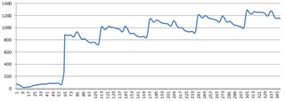
    Also I got I/Q data in MagPhase format and built graphs for different angles. And it's still seems like it doesn't switch correctly:

    What about  DFECTRL2 and SWITCHPATTERN? Maybe I configure them wrong?

Reply
  • So, I did:

    1. larger array (2048 val.)

    2. set DFEPACKET.MAXCNT = 2048

    3. TSAMPLESPACING == TSAMPLESPACINGREF = 125ns

    4 . different. setting for receiver and transmitter

    5 . DFECTRL2 = 0 for now (don't know which offsets i should put there)

    6. delete loop: "while (NRF_RADIO->EVENTS_PHYEND == 0U)"

    7. Add "packet" to validate received info.

    Here my full code:

    #ifndef RECEIVER
    #define RECEIVER    1
    #define TRANSMITTER !RECEIVER
    #endif
    #define MAXCNT1 2048
    uint32_t packet = 0;              /**< Packet to transmit. */
    int16_t i_q1[MAXCNT1];
    
    /**@brief Function for initialization oscillators.
     */
    void clock_initialization()
    {
        /* Start 16 MHz crystal oscillator */
        NRF_CLOCK->EVENTS_HFCLKSTARTED = 0;
        NRF_CLOCK->TASKS_HFCLKSTART    = 1;
    
        /* Wait for the external oscillator to start up */
        while (NRF_CLOCK->EVENTS_HFCLKSTARTED == 0)
        {
            // Do nothing.
        }
    
        /* Start low frequency crystal oscillator for app_timer(used by bsp)*/
        NRF_CLOCK->LFCLKSRC            = (CLOCK_LFCLKSRC_SRC_RC << CLOCK_LFCLKSRC_SRC_Pos);
        NRF_CLOCK->EVENTS_LFCLKSTARTED = 0;
        NRF_CLOCK->TASKS_LFCLKSTART    = 1;
    
        while (NRF_CLOCK->EVENTS_LFCLKSTARTED == 0)
        {
            // Do nothing.
        }
    }
    
    /**@brief Function for sending packet.
     */
    uint32_t send_packet(unsigned long freq, uint16_t *i_q)
    {
        // send the packet:
        uint32_t result = 0;
    
        NRF_RADIO->FREQUENCY = freq;
        // NRF_RADIO->DFEPACKET.PTR = i_q;
        NRF_RADIO->EVENTS_READY = 0U;
        NRF_RADIO->TASKS_TXEN   = 1;
        int a = 0;
    
        while (NRF_RADIO->EVENTS_READY == 0U) {}
        NRF_RADIO->EVENTS_END  = 0U;
        NRF_RADIO->TASKS_START = 1U;
    
        while (NRF_RADIO->EVENTS_END == 0U) {}
        nrf_delay_ms(50);
    
        NRF_RADIO->EVENTS_DISABLED = 0U;
        NRF_RADIO->EVENTS_PHYEND = 0U;
        // Disable radio
        NRF_RADIO->TASKS_DISABLE = 1U;
        while (NRF_RADIO->EVENTS_DISABLED == 0U) {}
        return result;
    }
    
    /**@brief Function for reading packet.
     */
    uint32_t read_packet(unsigned long freq, uint16_t *i_q)
    {
        uint32_t result = 0;
        int a = 0;
    
        NRF_RADIO->FREQUENCY = freq;
        NRF_RADIO->DFEPACKET.PTR = i_q;
        NRF_RADIO->DFEPACKET.MAXCNT = MAXCNT1;
        NRF_RADIO->EVENTS_READY = 0U;
        // Enable radio and wait for ready
        NRF_RADIO->TASKS_RXEN = 1U;
    
        while (NRF_RADIO->EVENTS_READY == 0U) {}
        NRF_RADIO->EVENTS_END = 0U;
        // Start listening and wait for address received event
        NRF_RADIO->TASKS_START = 1U;
        
        while (NRF_RADIO->EVENTS_END == 0U) {}
        nrf_delay_ms(100);
    
        if (NRF_RADIO->CRCSTATUS == 1U)
            result = packet;
        NRF_RADIO->EVENTS_DISABLED = 0U;
        NRF_RADIO->EVENTS_PHYEND = 0U;
        
        // Disable radio
        NRF_RADIO->TASKS_DISABLE = 1U;
        while (NRF_RADIO->EVENTS_DISABLED == 0U) {}
        return result;
    }
    
    static void print_logs()
    {
        LOG_DBG("%d", packet);
        for (int i = 0; i < MAXCNT1; i++)
                if (!(i % 2)) //print only 1,3,5 ... - phases
                    LOG_DBG(" %d", i_q1[i]);
        nrf_delay_ms(10); // to print all values we should wait a little
        LOG_DBG("\n");
        nrf_delay_ms(10);
    }
    
    /**
     * @brief Function for application main entry.
     * @return 0. int return type required by ANSI/ISO standard.
     */
    int main(void)
    {
        uint32_t err_code = NRF_SUCCESS;
    
        clock_initialization();
        // timer_init();
    
        // Set radio configuration parameters
        nrf_gpio_cfg_output(0x00000016); // (P0.22) - RF switch control pin - set as output prior
        radio_configure();
        NRF_RADIO->PACKETPTR = (uint32_t)&packet;
    
    
        LOG_DBG("Radio example started.\n");
    
        while (true)
        {
            #if RECEIVER
            read_packet(16UL, i_q1);
            print_logs();
            #else
            if (packet != 0)
            {
                send_packet(16UL, i_q1); // send at (2416MHz)
                LOG_DBG("Send %d!\n", packet);
                // packet = 0;
            }
            nrf_delay_ms(500);
            packet++;
            // __WFE();
            #endif
        }
    }

    void radio_configure()
    {
        // Radio config
        NRF_RADIO->TXPOWER   = (RADIO_TXPOWER_TXPOWER_Pos4dBm/*RADIO_TXPOWER_TXPOWER_0dBm*/ << RADIO_TXPOWER_TXPOWER_Pos);
        NRF_RADIO->FREQUENCY = 16UL;
        NRF_RADIO->MODE      = (RADIO_MODE_MODE_Ble_2Mbit/*RADIO_MODE_MODE_Nrf_1Mbit*/ << RADIO_MODE_MODE_Pos);
    
        // Radio address config
        NRF_RADIO->PREFIX0 =
            ((uint32_t)swap_bits(0xC3) << 24) // Prefix byte of address 3 converted to nRF24L series format
          | ((uint32_t)swap_bits(0xC2) << 16) // Prefix byte of address 2 converted to nRF24L series format
          | ((uint32_t)swap_bits(0xC1) << 8)  // Prefix byte of address 1 converted to nRF24L series format
          | ((uint32_t)swap_bits(0xC0) << 0); // Prefix byte of address 0 converted to nRF24L series format
    
        NRF_RADIO->PREFIX1 =
            ((uint32_t)swap_bits(0xC7) << 24) // Prefix byte of address 7 converted to nRF24L series format
          | ((uint32_t)swap_bits(0xC6) << 16) // Prefix byte of address 6 converted to nRF24L series format
          | ((uint32_t)swap_bits(0xC4) << 0); // Prefix byte of address 4 converted to nRF24L series format
    
        NRF_RADIO->BASE0 = bytewise_bitswap(0x01234567UL);  // Base address for prefix 0 converted to nRF24L series format
        NRF_RADIO->BASE1 = bytewise_bitswap(0x89ABCDEFUL);  // Base address for prefix 1-7 converted to nRF24L series format
    
        NRF_RADIO->TXADDRESS   = 0x00UL;  // Set device address 0 to use when transmitting
        NRF_RADIO->RXADDRESSES = 0x01UL;  // Enable device address 0 to use to select which addresses to receive
    
        // Packet configuration
        NRF_RADIO->PCNF0 = (PACKET_S1_FIELD_SIZE     << RADIO_PCNF0_S1LEN_Pos) |
                           (PACKET_S0_FIELD_SIZE     << RADIO_PCNF0_S0LEN_Pos) |
                           (PACKET_LENGTH_FIELD_SIZE << RADIO_PCNF0_LFLEN_Pos); //lint !e845 "The right argument to operator '|' is certain to be 0"
    
        // Packet configuration
        NRF_RADIO->PCNF1 = (RADIO_PCNF1_WHITEEN_Disabled << RADIO_PCNF1_WHITEEN_Pos) |
                           (RADIO_PCNF1_ENDIAN_Big       << RADIO_PCNF1_ENDIAN_Pos)  |
                           (PACKET_BASE_ADDRESS_LENGTH   << RADIO_PCNF1_BALEN_Pos)   |
                           (PACKET_STATIC_LENGTH         << RADIO_PCNF1_STATLEN_Pos) |
                           (PACKET_PAYLOAD_MAXSIZE       << RADIO_PCNF1_MAXLEN_Pos); //lint !e845 "The right argument to operator '|' is certain to be 0"
    
        // CRC Config
        //NRF_RADIO->CRCCNF = (RADIO_CRCCNF_LEN_Two << RADIO_CRCCNF_LEN_Pos); // Number of checksum bits
        NRF_RADIO->CRCCNF = (RADIO_CRCCNF_LEN_Disabled << RADIO_CRCCNF_LEN_Pos);
        if ((NRF_RADIO->CRCCNF & RADIO_CRCCNF_LEN_Msk) == (RADIO_CRCCNF_LEN_Two << RADIO_CRCCNF_LEN_Pos))
        {
            NRF_RADIO->CRCINIT = 0xFFFFUL;   // Initial value
            NRF_RADIO->CRCPOLY = 0x11021UL;  // CRC poly: x^16 + x^12^x^5 + 1
        }
        else if ((NRF_RADIO->CRCCNF & RADIO_CRCCNF_LEN_Msk) == (RADIO_CRCCNF_LEN_One << RADIO_CRCCNF_LEN_Pos))
        {
            NRF_RADIO->CRCINIT = 0xFFUL;   // Initial value
            NRF_RADIO->CRCPOLY = 0x107UL;  // CRC poly: x^8 + x^2^x^1 + 1
        }
    
        NRF_RADIO->MODECNF0 = RADIO_MODECNF0_RU_Fast << RADIO_MODECNF0_RU_Pos |
                             RADIO_MODECNF0_DTX_Center << RADIO_MODECNF0_DTX_Pos;
        NRF_RADIO->DFEMODE = RADIO_DFEMODE_DFEOPMODE_AoA;
    
    #if RECEIVER
        NRF_RADIO->DFECTRL1 =     31                                    << RADIO_DFECTRL1_NUMBEROF8US_Pos |
                                  RADIO_DFECTRL1_DFEINEXTENSION_CRC     << RADIO_DFECTRL1_DFEINEXTENSION_Pos |
                                  RADIO_DFECTRL1_TSAMPLESPACINGREF_125ns << RADIO_DFECTRL1_TSAMPLESPACINGREF_Pos |
                                  RADIO_DFECTRL1_TSAMPLESPACING_125ns   << RADIO_DFECTRL1_TSAMPLESPACING_Pos |
                                  RADIO_DFECTRL1_TSWITCHSPACING_1us     << RADIO_DFECTRL1_TSWITCHSPACING_Pos |
                                  RADIO_DFECTRL1_SAMPLETYPE_MagPhase    << RADIO_DFECTRL1_SAMPLETYPE_Pos;
        
        // I don't kwow which offsets I should put there
        NRF_RADIO->DFECTRL2 = 0 << RADIO_DFECTRL2_TSWITCHOFFSET_Pos |
                              0 << RADIO_DFECTRL2_TSAMPLEOFFSET_Pos;
        
        NRF_RADIO->PSEL.DFEGPIO[0] = 0x00000016; // (P0.22) - RF switch control pin
        NRF_RADIO->SWITCHPATTERN = 0x0; // before CTE - antenna 1
        NRF_RADIO->SWITCHPATTERN = 0x0; // reference - antenna 1
        NRF_RADIO->SWITCHPATTERN = 0x0; // slots 0, 2, 4... - antenna 1 switching
        // NRF_RADIO->SWITCHPATTERN = 0x0; // slots 0, 2, 4... - antenna 1 sampling
        // NRF_RADIO->SWITCHPATTERN = 0x1; // slots 1, 3, 5... - antenna 2 switching
        NRF_RADIO->SWITCHPATTERN = 0x1; // slots 1, 3, 5... - antenna 2 sampling
    
    #else
        NRF_RADIO->DFECTRL1 =     31                                    << RADIO_DFECTRL1_NUMBEROF8US_Pos |
                                  RADIO_DFECTRL1_DFEINEXTENSION_CRC     << RADIO_DFECTRL1_DFEINEXTENSION_Pos;
    #endif
    
        //NRF_RADIO->CTEINLINECONF = RADIO_CTEINLINECONF_S0MASK_Msk;
    }

    Also I got I/Q data in MagPhase format and built graphs for different angles. And it's still seems like it doesn't switch correctly:

    What about  DFECTRL2 and SWITCHPATTERN? Maybe I configure them wrong?

Children
  • You didn't enabled CRC. I don't know whether DFE can start without CRC if you configure RADIO_DFECTRL1_DFEINEXTENSION_CRC.

    larger array (2048 val.)

    a sample is two 16-bit values, you need 4096 16-bit cells. MAXCNT is in samples units (2048 is right).

    What about  DFECTRL2 and SWITCHPATTERN? Maybe I configure them wrong?

    SWITCHPATTERN seems to be correct. Do you have an ocsilloscope to look at P0.22 - is any switching takes place? Also you can try to configure RADIO_DFECTRL1_DFEINEXTENSION_Payload at receiver side to catch your payload as I/Q samples - you should see up/down slope for bits 0/1.

  • At the moment, I found out that there are problems with the antenna switch and with the external antenna. As soon as I eliminate them, I will continue to try

  • Hi,


    Have you actually looked at P0.22 using a scope or logic analyzer to see if it is toggling or not?


    Best regards,

    Andreas

  • I've some updates:

    1. RF switch and both antennas work correctly, switching occurs.

    2. I changed the settings a bit:

    Also I changed MAXCNT: NRF_RADIO->DFEPACKET.MAXCNT = MAXCNT1 / 2;

    NRF_RADIO->DFECTRL1 =     31                                    << RADIO_DFECTRL1_NUMBEROF8US_Pos |
                                  RADIO_DFECTRL1_DFEINEXTENSION_Payload     << RADIO_DFECTRL1_DFEINEXTENSION_Pos |
                                  RADIO_DFECTRL1_TSAMPLESPACINGREF_1us << RADIO_DFECTRL1_TSAMPLESPACINGREF_Pos |
                                  RADIO_DFECTRL1_TSAMPLESPACING_1us   << RADIO_DFECTRL1_TSAMPLESPACING_Pos |
                                  RADIO_DFECTRL1_TSWITCHSPACING_1us     << RADIO_DFECTRL1_TSWITCHSPACING_Pos |
                                  RADIO_DFECTRL1_SAMPLETYPE_MagPhase    << RADIO_DFECTRL1_SAMPLETYPE_Pos;
        
        // I don't kwow which offsets I should put there
        NRF_RADIO->DFECTRL2 = 0 << RADIO_DFECTRL2_TSWITCHOFFSET_Pos |
                              0 << RADIO_DFECTRL2_TSAMPLEOFFSET_Pos;
        
        NRF_RADIO->PSEL.DFEGPIO[0] = 0x00000016; // (P0.22) - RF switch control pin
        NRF_RADIO->SWITCHPATTERN = 0x0; // before CTE - antenna 1
        NRF_RADIO->SWITCHPATTERN = 0x0; // reference - antenna 1
        NRF_RADIO->SWITCHPATTERN = 0x0; // slots 0, 2, 4... - antenna 1 switching
        // NRF_RADIO->SWITCHPATTERN = 0x0; // slots 0, 2, 4... - antenna 1 sampling
        // NRF_RADIO->SWITCHPATTERN = 0x1; // slots 1, 3, 5... - antenna 2 switching
        NRF_RADIO->SWITCHPATTERN = 0x1; // slots 1, 3, 5... - antenna 2 sampling

    3. I expect that in this configuration, switching between antennas will occur after each sample. I have received the following phase graphs (0-45-90 degrees):

    Something still seems wrong...

  • Now you're receiving your payload as I/Q samples (RADIO_DFECTRL1_DFEINEXTENSION_Payload). I suggested it just to look at phase graph - whether you're receiving something meaningful, but with 1-us sampling we won't see anything.

    Did you try to enable CRC with RADIO_DFECTRL1_DFEINEXTENSION_CRC setting? And leave sampling interval of 0.125us for now - there will be much clear picture. There should be a continuous graph except the gap after first 8 us. Here you can see my results (though I use different algorithm to get phase value): samples 0-63 are for reference period, then the gap (first switching slot), then switching/sampling slots.

Related