This post is older than 2 years and might not be relevant anymore
More Info: Consider searching for newer posts

load-pull of BLE conducted power test

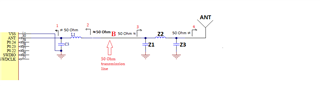
When we test the BLE conducted power, we find some phenomena, when IC power is setted to 0dBm, the active power loss is similar with passive path loss, it is consistent with the theoretical calculation; But if setting to 4dBm or 8dBm, the active power loss is more than passive path loss. The more detail test report in the attachment. And Base on these test data, when we set the IC power to 4dBm, it seems that the actual output power will chanBLT TX power report1.xlsxge under different load. Could you help to analysis the reason and share some load-pull information to us?

  • Hi, 

    do I understand your correctly; Your wondering why the loss is not the same for all the channels, and all the TX power settings? 

    The matching network components values are chosen to give desired output power and low enough harmonics, but this will very from channel to channel, and for what TX power setting your using, since the impedance won't be the same for all the settings. 

    So the matching components should be tuned for the specific design, and the TX power you aim to use. 

    So I would say that the measurements seems to be okay. 

    Have you done measurements before the diplexer, after C7, as well? We are happy to help with tuning. 

    Best regards,
    Kaja

  •  Thanks for your reply. 

    1. Actually,  I would like to konw why the insertion loss is different at different TX power setting. Does it be caused by the output power of IC change at different load impedance?


    2. As your reply, my understand is that the impedance of IC is diferent at different power setting, and different load impedance of IC  will cause different TX output power and harmonics, we had better tuned the different matching components to get the best performents at different power setting. Is it right? If it is right, could Nordic share the load pull of output power and harmonics information to us?especially at 4dBm level.

    3. Yes, we had test the measurements before the diplexer, after C7,  you can find the test result in the experiment3, the test point 2. and the power of point2-point1 is more than the passive loss when we setting 4dBm.

  • Hi Zager,

    the loss is different at the different TX power settings because the PA will not behave exactly the same for each setting. When tuning the components in the matching network the most important thing is the reduce the harmonics, and the harmonics effect will differ some between the TX power settings. 
    When you have found a match that gives you desired output power and the harmonics is low enough, the impedance is ~ 50 Ohm, and for the different power settings the desired impedance seen by the radio will be a bit different, that's why you should tune it based on the highest TX power setting you would like to use. 


    Again, we are happy to help you with the tuning process. 

    Best regards,
    Kaja

Related