This post is older than 2 years and might not be relevant anymore
More Info: Consider searching for newer posts

How can I use 2 or more PPI channels to control 1GPIO?

Hello 

I would like use at least 2PPI channels to control a GPIO.

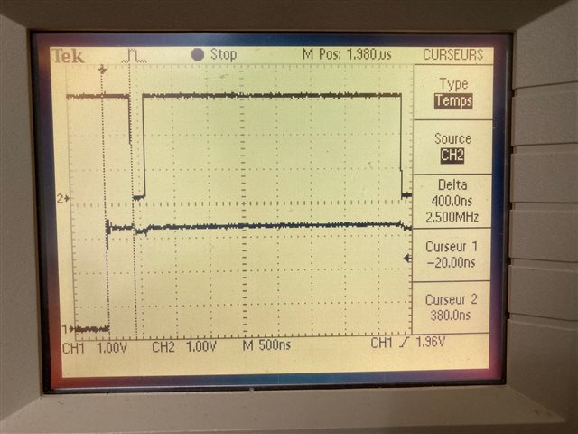
If PPI CH0&CH1 both setup, then GPIO_CTL just go high.

If PPI CH0 remarked, then GPIO_CTL go low

How to use 2ppi to control 1gpio?

The code as below

    uint32_t PPI_evt_addr;
    uint32_t PPI_task_addr;
    nrf_ppi_channel_t ppi_channel;	
	/* PPI CHANNEL0 SETUP	*/
	ppi_channel=NRF_PPI_CHANNEL0;
	nrf_drv_gpiote_out_config_t config_1=GPIOTE_CONFIG_OUT_TASK_HIGH;
    nrf_drv_gpiote_out_init(GPIO_CTL , &config_1);					
    nrf_drv_ppi_channel_alloc(&ppi_channel);														

	PPI_evt_addr = nrf_drv_timer_event_address_get(&TIMER1, NRF_TIMER_EVENT_COMPARE0);
    PPI_task_addr = nrf_drv_gpiote_out_task_addr_get(GPIO_CTL);								

    nrf_drv_ppi_channel_assign(ppi_channel, PPI_evt_addr, PPI_task_addr);
    nrf_drv_ppi_channel_enable(ppi_channel);							
    nrf_drv_gpiote_out_task_enable(GPIO_CTL);							

	/* PPI CHANNEL1 SETUP	*/
	ppi_channel=NRF_PPI_CHANNEL1;
	nrf_drv_gpiote_out_config_t config_0=GPIOTE_CONFIG_OUT_TASK_LOW;			
    nrf_drv_gpiote_out_init(GPIO_CTL , &config_0);								
    nrf_drv_ppi_channel_alloc(&ppi_channel);
		
    PPI_evt_addr = nrf_drv_timer_event_address_get(&TIMER2, NRF_TIMER_EVENT_COMPARE0);
    PPI_task_addr = nrf_drv_gpiote_out_task_addr_get(GPIO_CTL);						

    nrf_drv_ppi_channel_assign(ppi_channel, PPI_evt_addr, PPI_task_addr);
    nrf_drv_ppi_channel_enable(ppi_channel);							
    nrf_drv_gpiote_out_task_enable(GPIO_CTL);							

Parents
  • Hello,

    you cannot assign two GPIOTE channels to the same pin, that won't work. But you can control different tasks of a single GPIOTE channel (SET and CLR) from two different PPI channels.

  • Hi Dmitry

    How to setup ""a single GPIOTE channel (SET and CLR) from two different PPI channels"?

    My code as below. Thanks a lot.

    		
    		NRF_PPI->CH[0].EEP  = (uint32_t)&NRF_TIMER2->EVENTS_COMPARE[0];     
    		NRF_PPI->CH[0].TEP  = (uint32_t)&NRF_GPIOTE->TASKS_OUT[0];    
    	
    		NRF_PPI->CH[1].EEP  = (uint32_t)&NRF_TIMER2->EVENTS_COMPARE[1];     
    		NRF_PPI->CH[1].TEP  = (uint32_t)&NRF_GPIOTE->TASKS_OUT[0];     		
    
    		NRF_PPI->CH[2].EEP  = (uint32_t)&NRF_TIMER2->EVENTS_COMPARE[2];     
    		NRF_PPI->CH[2].TEP  = (uint32_t)&NRF_TIMER2->TASKS_STOP;				// Stop TIMER	
    	
    		NRF_PPI->CHEN       = (PPI_CHEN_CH0_Enabled << PPI_CHEN_CH0_Pos)	|
    													(PPI_CHEN_CH1_Enabled << PPI_CHEN_CH1_Pos)	|
    													(PPI_CHEN_CH2_Enabled << PPI_CHEN_CH2_Pos);
    													
    		NRF_GPIOTE->CONFIG[0] =((GPIOTE_CONFIG_MODE_Task << GPIOTE_CONFIG_MODE_Pos)
    															|(CVSD_CTL  << GPIOTE_CONFIG_PSEL_Pos)
    															|(GPIOTE_CONFIG_POLARITY_Toggle << GPIOTE_CONFIG_POLARITY_Pos)
    															|(GPIOTE_CONFIG_OUTINIT_High     << GPIOTE_CONFIG_OUTINIT_Pos)); 
    

    Austin

  • For example, to make a low-polarity pulse:

    		NRF_PPI->CH[0].EEP  = (uint32_t)&NRF_TIMER2->EVENTS_COMPARE[0];     
    		NRF_PPI->CH[0].TEP  = (uint32_t)&NRF_GPIOTE->TASKS_CLR[0];    
    	
    		NRF_PPI->CH[1].EEP  = (uint32_t)&NRF_TIMER2->EVENTS_COMPARE[1];     
    		NRF_PPI->CH[1].TEP  = (uint32_t)&NRF_GPIOTE->TASKS_SET[0];     		
    

  • Hi Dmitry

      Thanks a lot! You rescue me!

      If I use "(uint32_t)&NRF_GPIOTE->TASKS_OUT[0];" , it cost timing around 1us.

      I use "(uint32_t)&NRF_GPIOTE->TASKS_CLR[0]; " or "(uint32_t)&NRF_GPIOTE->TASKS_SET[0];" , the timing cost is almost zero!

    -------------------------------------------------------------------------------

       I have a new problem as below.

    void TIMER2_config(void)
    {
      NRF_TIMER2->TASKS_STOP = 1;	// Stop timer
      NRF_TIMER2->MODE = TIMER_MODE_MODE_Timer;  // taken from Nordic dev zone
      NRF_TIMER2->BITMODE = (TIMER_BITMODE_BITMODE_08Bit << TIMER_BITMODE_BITMODE_Pos);
      NRF_TIMER2->PRESCALER = 0;	// 1us resolution
      NRF_TIMER2->TASKS_CLEAR = 1; // Clear timer
      NRF_TIMER2->CC[0] = 1;					//*62.5ns
      NRF_TIMER2->CC[1] = 2;					//*62.5ns
    NRF_TIMER2->CC[2] = 62;					//*62.5ns	
    	
      NRF_TIMER2->INTENSET = (TIMER_INTENSET_COMPARE0_Enabled << TIMER_INTENSET_COMPARE0_Pos) |
    													(TIMER_INTENSET_COMPARE1_Enabled << TIMER_INTENSET_COMPARE1_Pos) | 	
    													(TIMER_INTENSET_COMPARE2_Enabled << TIMER_INTENSET_COMPARE2_Pos);  // taken from Nordic dev zone
      NRF_TIMER2->SHORTS = (TIMER_SHORTS_COMPARE0_CLEAR_Disabled << TIMER_SHORTS_COMPARE0_CLEAR_Pos)	|
    											 (TIMER_SHORTS_COMPARE1_CLEAR_Disabled << TIMER_SHORTS_COMPARE1_CLEAR_Pos)	|
    											 (TIMER_SHORTS_COMPARE2_CLEAR_Enabled << TIMER_SHORTS_COMPARE2_CLEAR_Pos);
    }
    void PPI_config(void)
    {
    		/*when TIMER2 CC0 = NUM , then pin =0*/
    		NRF_PPI->CH[0].EEP  = (uint32_t)&NRF_TIMER2->EVENTS_COMPARE[0];     
    //		NRF_PPI->CH[0].TEP  = (uint32_t)&NRF_GPIOTE->TASKS_OUT[0];    
    			NRF_PPI->CH[0].TEP  = (uint32_t)&NRF_GPIOTE->TASKS_CLR[0];    
    	
    		/when TIMER2 CC1 = NUM , then pin = 1*/
    		NRF_PPI->CH[1].EEP  = (uint32_t)&NRF_TIMER2->EVENTS_COMPARE[1];     
    //		NRF_PPI->CH[1].TEP  = (uint32_t)&NRF_GPIOTE->TASKS_OUT[0];     		
    			NRF_PPI->CH[1].TEP  = (uint32_t)&NRF_GPIOTE->TASKS_SET[0];     		
    		/*when TIMER2 CC2 = NUM then TIMER2 stop*/
    		NRF_PPI->CH[2].EEP  = (uint32_t)&NRF_TIMER2->EVENTS_COMPARE[2];     
    		NRF_PPI->CH[2].TEP  = (uint32_t)&NRF_TIMER2->TASKS_STOP;				// Stop TIMER	
    	
    		NRF_PPI->CHEN       = (PPI_CHEN_CH0_Enabled << PPI_CHEN_CH0_Pos)	|
    													(PPI_CHEN_CH1_Enabled << PPI_CHEN_CH1_Pos)	|
    													(PPI_CHEN_CH2_Enabled << PPI_CHEN_CH2_Pos);
    													
    		NRF_GPIOTE->CONFIG[0] =((GPIOTE_CONFIG_MODE_Task << GPIOTE_CONFIG_MODE_Pos)
    															|(CVSD_CTL  << GPIOTE_CONFIG_PSEL_Pos)
    															|(GPIOTE_CONFIG_POLARITY_Toggle << GPIOTE_CONFIG_POLARITY_Pos)
    															|(GPIOTE_CONFIG_OUTINIT_High     << GPIOTE_CONFIG_OUTINIT_Pos)); 
    }
    
    		int8_t bit_cnt;
    		
    		bit_cnt++;
    		bit_cnt = bit_cnt & 0x01;
    	
    		bool	DIN_bit ;
    		DIN_bit = bit_cnt;					    //for test
    
    		NRF_TIMER2->CC[0] = 1;					
    		NRF_TIMER2->CC[1] = 3;					
    		NRF_TIMER2->CC[2] = 62;					
    
    		nrf_gpio_pin_write (GPIO14, DIN_bit );	
    
    		NRF_TIMER2->TASKS_START = 1;	// Start TIMER	


    GPIO14 is a sign, for check how log PPI CH0 works.

    The question is ,

     After "NRF_TIMER2->TASKS_START = 1;", the timing pass 400ns then PPI CH0 works.

     How could it takes so much time?

    In my imagine, PPI CH0 should response in 100ns , because CC[0]=1.

    Austin

    PPI CH0 response time is 400ns

  • I couldn't get your goal..  if you need to respond to an external signal as quick as possible, you should start a timer also using PPI, but if it's a response to a software event, you cannot guarantee such a tight timings. Your code is compiled into a sequence of assembly instructions, their count depends on compiler and its settings (especially optimization level), and they cannot be executed in a zero time. Also the timer needs some time to start up.

Reply
  • I couldn't get your goal..  if you need to respond to an external signal as quick as possible, you should start a timer also using PPI, but if it's a response to a software event, you cannot guarantee such a tight timings. Your code is compiled into a sequence of assembly instructions, their count depends on compiler and its settings (especially optimization level), and they cannot be executed in a zero time. Also the timer needs some time to start up.

Children
Related