This post is older than 2 years and might not be relevant anymore
More Info: Consider searching for newer posts

Erasing gazell pairing memory.

Environment - windows 10, ses release 4.12 nRFconnect programmer 3.3.3 using gnu C nRF52840 dongle programming with DFU. No softdevice, Gazell only.

I have two hex files, one containing my nrf52840 dongle program and the other containing the program plus a section erasing 4k of memory from 15000
With the same difference between .hex files (but obviously not identical .hex files) using ses and Jlink on the PCA10056 dev kits, both .hex work just fine.

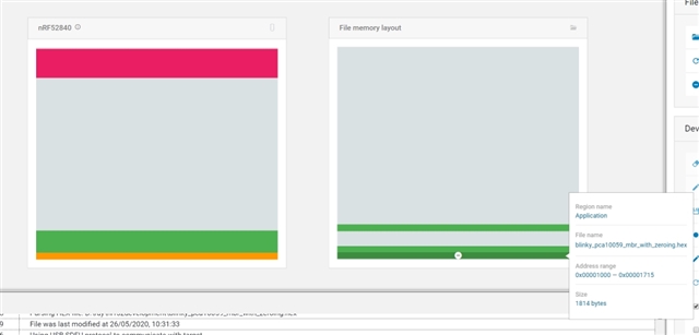
If I use nRFConnect v3.3.3 programmer to load the one containing just the program onto a dongle, all runs just fine.
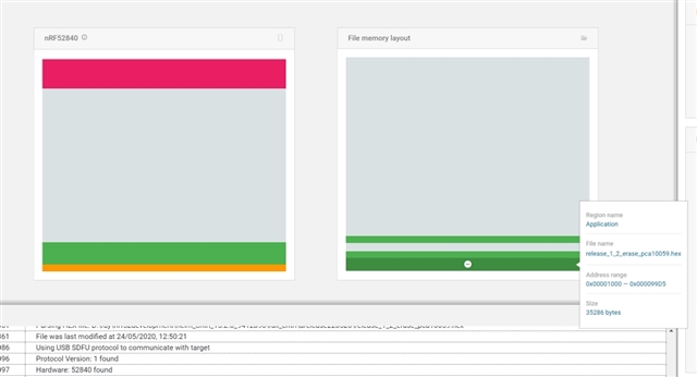
If I use nRFConnect programmer to load the one which also erases the 4k of memory, the program does not run at all, when powering up the dongle it goes into bootloader mode without pressing the reset button.
.
They are built using ses. The only difference in the build is in the file "flash_placement.xml".
The only difference in that file is in the line:
<ProgramSection alignment="4" keep="Yes" load="No" name=".GZP_PARAMS" start = "0x00015000" size="0x1000" />
which is changed to:
<ProgramSection alignment="4" keep="Yes" load="Yes" name=".GZP_PARAMS" start = "0x00015000" size="0x1000" />

There is not a single character of difference in either the .map file or the section of the .hex file which contains the program.

The only difference in the hex file is a section which looks like:

:020000021000EC
:10500000FFFFFFFFFFFFFFFFFFFFFFFFFFFFFFFFB0
:10501000FFFFFFFFFFFFFFFFFFFFFFFFFFFFFFFFA0
:10502000FFFFFFFFFFFFFFFFFFFFFFFFFFFFFFFF90
:10503000FFFFFFFFFFFFFFFFFFFFFFFFFFFFFFFF80
:10504000FFFFFFFFFFFFFFFFFFFFFFFFFFFFFFFF70

               *
               *
               *
:105FA000FFFFFFFFFFFFFFFFFFFFFFFFFFFFFFFF01
:105FB000FFFFFFFFFFFFFFFFFFFFFFFFFFFFFFFFF1
:105FC000FFFFFFFFFFFFFFFFFFFFFFFFFFFFFFFFE1
:105FD000FFFFFFFFFFFFFFFFFFFFFFFFFFFFFFFFD1
:105FE000FFFFFFFFFFFFFFFFFFFFFFFFFFFFFFFFC1
:105FF000FFFFFFFFFFFFFFFFFFFFFFFFFFFFFFFFB1

(I missed out a lot of them because they are boring).
The first line sets the start address and the subsequent lines fill them with FF.

Just to prove a point, if I edit out the above lines erasing the memory from the hex file and then use nrfconnect programmer to write the resulting .hex the program runs just fine.
If I write the program containing the erase, and then re-write it with the one without the erase, then it works just fine AND it looks like the erase actually worked i.e. I have to re-pair the client with the server dongle.

I then tried to edit out the application and keep JUST the erase commands - Ah, nRF connect knows better than me because it then asked me what soft device I wanted (that being none which wasn't allowed) and refuse to program the dongle unless I gave an answer.

Can anyone throw a light on just how to use nRFconnect programmer to set some memory to FFs in the region 15000 for 4K and actually have a working dongle.

If a Nordic employee is interested, I can send you the .hex files.


Regards, Ray Foulkes


PS - I do have some options still:
a) (assuming that nrfutil does not have the same limitations) switch to command line programming using some Bash scripting.
b) tell the end user to load the non-working program, then the working program and the pairing memory will have been erased - very amateurish but it works.
c) do what I have done for the device end - make it possible to erase 4K of memory when starting the dongle with finger on the button instead of just the device pairing record.
d) persuade Nordic to make a gui program that just does what it is told, and doesn't try to be over clever (or try to make one myself)

PPS, It would be REALLY, REALLY nice if someone could document the actual logic used by nRFconnect programmer in the user guide. It pretends to be able to load whatever you give it (it does not say otherwised) but it is blatantly not true, well, it might load it, but it somehow prevents it from running. I have spent a week trying to understand what was happening.

In order to save me much frustration and time, can someone answer the question "If I try to use the command line nrfutil will I simply hit the same obstacle (i.e. does nrfConnect programmer simply pass on the defects of nrfutil??) "

Parents
  • Hi Raymond, 

    The protocol that nRF Connect uses to program the nRF528540 dongle is the DFU protocol. The nRF Connect automatically switch the dongle to bootloader mode and flash the board via the bootloader. The USB bootloader can be found here: https://infocenter.nordicsemi.com/topic/sdk_nrf5_v16.0.0/ble_sdk_app_open_bootloader.html?cp=7_1_4_4_2

    The protocol is here: https://infocenter.nordicsemi.com/topic/sdk_nrf5_v16.0.0/lib_dfu_transport.html?cp=7_1_3_5_2

    The nRF Connect when given a hex file, will first convert it to a binary file. This is the place where your 4K of all 0xFFFFFFFF is realized. My assumption is that in the binary generated, there will be all 0xFFFFFFFF all the way from the end of your application until address 0x15FFF. 

    NRF Connect will send all these 0xFFFFFFFF to the bootloader, and the bootloader will also write 0xFFFFFFFF into the chip, there will be no check.

    The question is why it worked for the firmware with no 4K of blank at 0x15000 and it didn't work when there is that 4K. 

    What we can do is to read out the hex dump from the dongle, and check the difference. 

    From what you described that the device enter bootloader without going to the application, it may suggest that the CRC check was failed. 

    If you can send us a sample hex files of a very simple application (blinking LED for example) one works and one doesn't we can try to figure out the issue. 

    I assume your application already made with start address at 0x1000 ? (to avoid the MBR)

Reply
  • Hi Raymond, 

    The protocol that nRF Connect uses to program the nRF528540 dongle is the DFU protocol. The nRF Connect automatically switch the dongle to bootloader mode and flash the board via the bootloader. The USB bootloader can be found here: https://infocenter.nordicsemi.com/topic/sdk_nrf5_v16.0.0/ble_sdk_app_open_bootloader.html?cp=7_1_4_4_2

    The protocol is here: https://infocenter.nordicsemi.com/topic/sdk_nrf5_v16.0.0/lib_dfu_transport.html?cp=7_1_3_5_2

    The nRF Connect when given a hex file, will first convert it to a binary file. This is the place where your 4K of all 0xFFFFFFFF is realized. My assumption is that in the binary generated, there will be all 0xFFFFFFFF all the way from the end of your application until address 0x15FFF. 

    NRF Connect will send all these 0xFFFFFFFF to the bootloader, and the bootloader will also write 0xFFFFFFFF into the chip, there will be no check.

    The question is why it worked for the firmware with no 4K of blank at 0x15000 and it didn't work when there is that 4K. 

    What we can do is to read out the hex dump from the dongle, and check the difference. 

    From what you described that the device enter bootloader without going to the application, it may suggest that the CRC check was failed. 

    If you can send us a sample hex files of a very simple application (blinking LED for example) one works and one doesn't we can try to figure out the issue. 

    I assume your application already made with start address at 0x1000 ? (to avoid the MBR)

Children
  • Hello again Hung Bui, OK, now I am baffled - I am unable to replicate the problem using Blinky. I used V16 SDK, recompiled blinky for the dongle, then edited the .hex file to include the zeroing of the memory from 15000. When I load it into nRFconnect programmer it shows two segments - one the original blinky and the section that I want reset. I load this into a clean dongle and it works just fine. I load my program over it and that only goes back to DFU.

    I include some images (I hope). The first are blinky examples showing the result in the programmer:

    Programmer before writing.

    The above shows the programmer after loading the file but before writing (for the second time) to the dongle. It shows the band of memory to be set to FFFFFFFF above the program.

    Showing the dimensions of the area to

    The above is the same showing the size of the FFFFFFFF band. Just a note - there seems to be no relation with respect to scaling between the two windows. i.e. Bytes to height varies from window to window.

    My app

    The above shows my application loaded into the programmer. When this is written and the dongle re-powered, it just goes into DFU mode immediately.

    I will write a bit more in a subsequent response - I am a bit disappointed that I cannot replicate the problem in Blinky. Maybe I will try with a Gazell example next. (post - note OOPS I cannot do that because the gazell examples do not include the pca10059 nor do they support SES and that would be a big job for me to covert them).

  • You wrote

    What we can do is to read out the hex dump from the dongle, and check the difference. 

    I do not know  how to read the memory of a Dongle. When used in DFU mode, the menu items for reading and saving the contents of the memory of the dongle are always greyed out. The only buttons ever enabled are "reset" and "write". I have confirmed with Nordic that that is always the case. You cannot do anything but write to the dongle using the programmer.

    I do have two hardware sdk so I do know that, if I added a socket to the dongle and had the appropriate lead, I maybe could use the Jlink buried in the sdk to read the memory but I don't have the components at the moment to do that.

    I assume your application already made with start address at 0x1000 ? (to avoid the MBR)

    Yes, you will see that from the screen captures that I posted. Also, please remember, without the zeroing the memory, the application works fine as does the DFU after I press the reset button to trigger it. (my application does not know about DFU). I have checked very carefully, there is no difference in the .hex files in the part which contain the program between the ones that FFFFFFFF the memory and the ones that do not.

    The question is why it worked for the firmware with no 4K of blank at 0x15000 and it didn't work when there is that 4K. 

    Exactly so. Why does blinky work, and not my application?

    My assumption is that in the binary generated, there will be all 0xFFFFFFFF all the way from the end of your application until address 0x15FFF.

    That would be fine with me.

    I am wondering whether to give up on trying to reset the memory at program load time using the programmer. It will only be of importance in the case where the dongles are being re-purposed i.e. writing a new program and changing from Gazell device to host or vice versa. I might be able to write a program to detect the change of role and zero the memory myself during initialisation.

    Thank you for the references for the DFU - I had a quick look, but studying that will take more than a few minutes on a Tuesday morning!

    Thank you for your attention,

    Regards, Ray

  • Hi Ray,

    You can read the hex dump by connecting a programmer (nRF52 DK) to the dongle. This requires you to solder the header on port P1. and then use a 10 pin cable to connect the debug out port on the DK to this header. This way you can access the dongle flash directly without using the bootloader (you can program the dongle ). Then you can read the code out either using nrf connect or use "nrfjprog.exe --readcode" command line tool. 

    But I think I found what could be wrong here. It's the CRC check failed. Most likely because your code will write to the 4K "blank area" to store gazell data. And because of that CRC will fail. The bootloader expecting your application as a whole from 0x1000 to 0x15FFF. And any modification to flash in this range will result in CRC check fail on booting. And the bootloader will enter DFU mode. 

    When you don't include the "blank area" the bootloader wont check the address from 0x1000 to 0x15FFF but only to the last address of your code, meaning writing to 0x15000 won't affect CRC. 

    So I think the easiest solution is still to use 2 binaries, one to erase flash, and one to start normal application. Or you can include a feature in the code to erase that 4kB of data when you press a button or when you send a command. For example, when application detect you hold SW1 when plug the dongle in USB port, it erases the 4kB flash. 

  • Hi Hung Bui. Thanks very much for the explanation. I did not understand the consequences of the bootloader considering my data area as part of the program. I imagined that the start address of my program was simply hard-wired into the hardware for start-up once I had written the NVRAM with my program. I did not realise that, after programming with the DFU bootloader, the bootloader still intercepted the start-up sequence and carried out checks. I thought to make that happen I had to add bootloader functions to my program. Now all is clear - once the bootloader is loaded onto a processor it ALWAYS runs first, even if it doesn't enable the USB port if it finds a valid program loaded.

    I did know about the use of the DK to both load and examine memory but unfortunately I am stuck a very long way from my electronic workshop containing all my sockets, cables etc. The only thing I brought with me was some dongles and the DKs. I could start ordering parts but there is no point if the bootloader is guaranteed to fail the crc check after Gazell writes into the NVRAM.

    So I think the easiest solution is still to use 2 binaries, one to erase flash, and one to start normal application.

    That was my chosen work-around.

    Or you can include a feature in the code to erase that 4kB of data when you press a button or when you send a command.

    I already use the white button on the device end to permit re-pairing but that is used in the field, not during device preparation.

    The reason I was trying to do this in one step is not for me or some other techie but because there may well be a thousand or two of these being programmed (and potentially re-programmed and re-purposed) by people who are not that technologically inclined. Every step I add, including holding finger on button when powering up, just adds another operation to go wrong.

    I have already labelled one .hex as "erase.hex" so for re-purposing, they will just have to load that first. Unfortunately the volumes are not sufficient to warrant setting up an auto-programming system.

    Thank you once again for your efforts - I really appreciate the help of the community - this software and hardware environment is not the simplest to understand.

Related