Dear Nordic user,
We are under development with nRF52810-QCAA.
The first board has been make and is being tested.
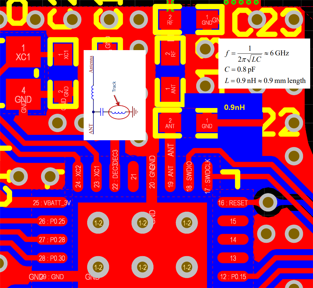
However, after making the board, I noticed that the important part mentioned in the datasheet was not applied.
It is the important information (comment in the blue box) mentioned in 7.3.9 PCB layout example of nRF52810_PS_v1.3.pdf.

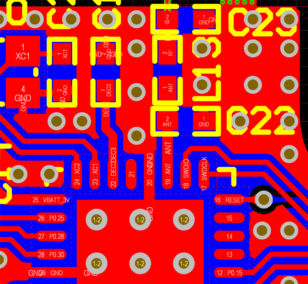
Below is the antenna connection screenshot of our board.
GND is directly connected to the nRF52810's 20 pin, and C22 is connected to the other GND.
- component value are C22/0.8pF, L13/3.9nH, C23/N.C
I’m not sure how much this affects the harmonic filtering and whether we should take the risk of not passing regulation tests.
1. Is this an important comment that must be followed? - in 7.3.9 PCB layout example of nRF52810_PS_v1.3.pdf
1.1 Please explain the situation that may occur if I do not follow the important comment.
2. If not, what steps should I take to improve other than modifying the PCB?
3. What instruments or specifications are needed to perform the procedure?
4. Is the best way to change the PCB design?
Thanks in advance for your answer.
Sungsuk Han.


