Beware that this post is related to an SDK in maintenance mode
More Info: Consider nRF Connect SDK for new designs
This post is older than 2 years and might not be relevant anymore
More Info: Consider searching for newer posts

How to Generate Bi-Phasic PWM with interpulse delay and variable Duty Cycle?

Hello All,

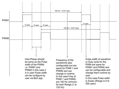
I want to generate Bi-Phasic two PWMs with 180 degree interphase delay and variable Duty Cycle with variable frequency upto 250 Hz in nRF52810 SoC.

Can you please suggest the mechanism as far as firmware programming is concerned!

Thank you in advance 

Parents
  • Hello,

    Have you seen the PWM driver example from the SDK? It demonstrates a range of different PWM waveforms and how to implement them. The PWM library example demonstrates how to generate the two waveforms with 180 degree interphase delay.
    Furthermore, you can read about the nRF52810 SoC PWM driver and its usage in the PWM Driver documentation, and the PWM API Reference.

    Can you please suggest the mechanism as far as firmware programming is concerned!

    I am not sure what you mean here - are you asking how to get started on the implementation(getting started with the nRF52810 SoC?) or are you asking about the resources I referenced above?

    Please let me know if this does not answer your question,

    Best regards,
    Karl


  • Ok so I am bit confuse over PWM Library an PWM Driver!

    Which should i use for my sort of application in which the freq, duty cycle changes with variable inter phase delay!

    Please help to clear out confusion!

  • Hey Karl,


    Actually We are making the frequency simulator using Bluetooth application and user can control by Mobile Application, following are my parameters basically to control from the app:

    1) Frequency user can vary from 1 to 120 Hz

    2) Pulse Width from 0 to 250 usec

    Can you please suggest what should I use for such application .

  • Hello,

    I understand, so the user will use their phone to set the frequency and duty cycle of the PWMs.
    In that case, you might want to create a custom service to hold these characteristics, and to make them available to your mobile application.
    To get started on how to create a custom service I highly recommend this tutorial - it takes your through the process of creating a customer service, and the following characteristics tutorial goes through how to add any characteristic to your service. Then, you could create a "PWM control service" with the characteristics "Frequency" and "Pulse width", and when those characteristics are written to you will either initialize a new PWM waveform or change the duty cycle of an existing PWM waveform - both of which as discussed in my previous comment.
    When this is done, you could either immediately use the nRF Connect mobile application to control your device, or you could write a custom smartphone application to control it.

    Are you familiar with nRF development, and do you have access to a Development Kit?

    Best regards,
    Karl

  • Hello Karl,

    Thank you for overall guidance ,

    I already done with Bluetooth services and characteristics as you just described ,

    Now i am really confused with implementation of the adaptive frequency and duty cycle waveform with inter-phase adaptive delays.

    I hope you got my point as if you said for reverse polarity but it cant serve my problem as i want adaptive inter-phase delay not just 180 straight.

    Are you familiar with nRF development, and do you have access to a Development Kit?

    Yes I have good amount of nRF development as far as services and charactertics for BLE is concerned, I have access to DK board nRF52-DK.

    We have already placed nRF52810 in our carrier board as for final product implmentation.

    I just stuck for this part now in development i.e. of waveforms.

    1) Frequency user can vary from 1 to 120 Hz

    2) Pulse Width from 0 to 250 usec

    Can you please suggest what should I use for such application .

  • Hello, 

    Smit said:
    Thank you for overall guidance

    No problem at all, I am happy to help!

    Smit said:
    Now i am really confused with implementation of the adaptive frequency and duty cycle waveform with inter-phase adaptive delays.

    I hope you got my point as if you said for reverse polarity but it cant serve my problem as i want adaptive inter-phase delay not just 180 straight.

    Sorry, I did not see that you wanted to do adaptive inter-phase delays as well. This is not a problem either, because you can just offset the timer channels capture/compare(CC) register to phase shift one of the PWM waveforms.

    Smit said:
    Yes I have good amount of nRF development as far as services and charactertics for BLE is concerned, I have access to DK board nRF52-DK.

    That is great to hear, thank you for letting me know. This will make things much easier.

    Smit said:
    Can you please suggest what should I use for such application

    I will try to be more specific about how you could proceed to have the configurable PWM waveform demonstrated on a DK LED:

    1. Begin with the Nordic UART Peripheral example ( or another custom project that includes a service you can use to communicate with the device )
    2. Follow the steps in "Generate a low-power PWM signal" from the PWM Library documentation to setup an arbitrary / default PWM instance.
    3. Setup a BLE command using your service to update the PWM, if you are using the Nordic UART as base it could look like:
            - a FREQ field to control frequency, implement by having it app_pwm_disable the active PWM, and then init and enable a new PWM instance with the updated config.
            - a DUTY field to control duty cycle, implement by making a call to app_pwm_channel_duty_set
            - a PHASE field to control phase, implement by offsetting the value of the capture/compare register of the timer in use. So, for a PWM instance 1 it is using TIMER1, which means that the register must be offset by writing to its capture compare register like so : NRF_TIMER3->CC[cc_channel] = cc_value
    By setting the CC value before the channel is enabled, you will offset the counter - creating the phase shift. For convenience, you might want to create a function that translates the desired phase shift from degrees to cc_value.

    You could either implement this as a FREQ-DUTY-PHASE string sent over UART, or you could implement it as 3 characteristics of a "PWM signal" service.

    Note that all PWMs on a single app_pwm_library instance all uses the same clock source, so the frequency of the PWM's will be the same for all app_pwm_init'ed channels.
    If you wish to have independent PWM frequencies, you will need to create multiple APP_PWM_INSTANCEs.

    Please do not hesitate to let me know if anything still should be unclear, or if you encounter any other questions or issues!

    Best regards,
    Karl

  • Ok Karl,

    Thank you for prompt reply,


    Let me share my overall concept behind this or output of waveform as below.

    Here There are two GPIOs in which i want to form waveforms as above 

    1) PWM 1 and PWM 2 : That has frequency as well as duty cycle if PWMs or pulse widths as user perspective. NOTE: PWM1 and PWM2 should have same freq and duty cycle of pulse width .
    Range for Freq user can vary from Application is 1 to 150 Hz and Pulse width would be 0 to 250 usec.

    2) Interphase delay or delay between two PWMs would be exactly same as the Pulse width or duty cycle of the PWMs .

    I have got all two parameters from the user ie frequency as well as Pulse width.
    Just clear me the concept of implementation to produce the waveforms on CRO or physically in nRF as above.

Reply
  • Ok Karl,

    Thank you for prompt reply,


    Let me share my overall concept behind this or output of waveform as below.

    Here There are two GPIOs in which i want to form waveforms as above 

    1) PWM 1 and PWM 2 : That has frequency as well as duty cycle if PWMs or pulse widths as user perspective. NOTE: PWM1 and PWM2 should have same freq and duty cycle of pulse width .
    Range for Freq user can vary from Application is 1 to 150 Hz and Pulse width would be 0 to 250 usec.

    2) Interphase delay or delay between two PWMs would be exactly same as the Pulse width or duty cycle of the PWMs .

    I have got all two parameters from the user ie frequency as well as Pulse width.
    Just clear me the concept of implementation to produce the waveforms on CRO or physically in nRF as above.

Children
  • Hello,

    From your diagram it apppears that the two PWM's will always have the same frequency - this enables you to only use 1 timer instance, as mentioned in my previous comment. From your diagram it also seems that the two PWMs always will have the same frequency and duty cycle - only the inter-phase offset changes between them?

    Smit said:
    I have got all two parameters from the user ie frequency as well as Pulse width.

    If you are using both "Pulse width" and "duty cycle" to refer to the duty cycle of the PWM, I would prefer that you only use the term duty cycle. If you are referring to something else when you say "pulse width", please elaborate what this is.

    Smit said:
    Just clear me the concept of implementation to produce the waveforms on CRO or physically in nRF as above.

    I generally outlined the implementation in my previous comment. Is there a particular step or part of the outline which you would like me to detail? I would suggest that you flash your DK with the pwm library example and play around with the different functions from the documentation to familiarize yourself with its functionality. Start with the unmodified example - observe its function and look into its code for how it is generated, then proceed with modifiying to code to generate different PWM waveforms.
    If you are already familiar with implementing and using BLE services and characteristics then you may implement the outline from my previous comment as three characteristics instead of an UART command.

    Best regards,
    Karl

  • From your diagram it also seems that the two PWMs always will have the same frequency and duty cycle - only the inter-phase offset changes between them?

    Actually Interphasing delay should be same as the duty cycle for the PWM.

    So if user changes the duty cycle the interphasic delay also changes and should be same as duty cycle of the PWM.

    both "Pulse width" and "duty cycle" to refer to the duty cycle of the PWM, I would prefer that you only use the term duty cycle. If you are referring to something else when you say "pulse width", please elaborate what this is.

    Ok now Suppose the diagram I saw you is waveform that I want to create using two GPIOs so there should be two possibility whether by PWM (duty Cycle) or Timer (pulse width) .

    Now as per User perspective whether to use PWM or Timer the final result would be the pulse width if we coin the term using Timer and if we use PWM then Duty Cycle.

    But the end result should be as per posted diagram.

    I hope i make it more simple now to make you understand.

    Please suggest me the option to generate the waveform using two GPIOs and interphase delay.

    I have tried old school method .

    Method as below I have used two timers timer 0 and timer 1.
    first for creating frequency of msec timer (timer 1) and second is to create the pulse width with usec timer (timer 0).

     Interrupt handler for timer 1 msec timer for creating frequency .

    static void timer1_event_handler(nrf_timer_event_t event_type, void * p_context)
    {
        m_counter = 0;
        nrf_drv_timer_resume(&m_timer0);    
    
    }

    So Interrupt handler for timer 0 usec timer for creating pulse widths and  Interphase delay .

    static void timer0_event_handler(nrf_timer_event_t event_type, void * p_context)
    {
        ++m_counter;
        if(m_counter > 3)
        {
          nrf_drv_timer_pause(&m_timer0);
          bsp_board_led_off(BSP_BOARD_LED_0);
          bsp_board_led_off(BSP_BOARD_LED_1);
    
        }
        else
        {
          switch (m_counter)
          {
            case 1:
              bsp_board_led_on(BSP_BOARD_LED_0);
              bsp_board_led_off(BSP_BOARD_LED_1);
            break;
            case 2:
              bsp_board_led_off(BSP_BOARD_LED_0);
              bsp_board_led_off(BSP_BOARD_LED_1);
            break;
            case 3:
              bsp_board_led_off(BSP_BOARD_LED_0);
              bsp_board_led_on(BSP_BOARD_LED_1);
            break;
            default:
              bsp_board_led_off(BSP_BOARD_LED_0);
              bsp_board_led_off(BSP_BOARD_LED_1);
            break;
          }
        }
    }
    

    But in the above code i didnt get the resolution of 1usec as pulse width and interphasic delay .
    It might be due to GPIO toggling latency or internal delay.


    Can you please elaborate and please share the other method for the same 

  • Hello again,

    In the project you set up for the TIMER approach, did you have the SoftDevice enabled?
    Bear in mind that the SoftDevice uses timer0, and it will block off access from the application layer.
    Instead, you should use TIMER1 and TIMER2.

    Smit said:
    Actually Interphasing delay should be same as the duty cycle for the PWM.

    So if user changes the duty cycle the interphasic delay also changes and should be same as duty cycle of the PWM.

    I understand. This would be the same as calculating the duty cycles length in time, and adding that as an offset to the CAPTURE/COMPARE register, like I referenced in my previous comment.

    Smit said:
    But in the above code i didnt get the resolution of 1usec as pulse width and interphasic delay .
    It might be due to GPIO toggling latency or internal delay.

    Yes, that might well be the reason. I would not recommend using software PWM's when you have access to hardware for PWM generation along with the app_pwm library.

    Smit said:
    Can you please elaborate and please share the other method for the same

    The PWM library documentation includes a usage section, that demonstrates how you can setup a PWM waveform on the LEDs.
    You will then need to implement the steps for changing the frequency and duty cycle as described in my previous reply.
    Please attempt this, and post the code if you are not able to achieve the desired functionality.

    Best regards,
    Karl

Related