This post is older than 2 years and might not be relevant anymore
More Info: Consider searching for newer posts

Unable to toggle GPIO P0.0 or P0.1 with Zephyr

Working with nrf52832_mdk and using basic GPIO functionality, I am unable to toggle the GPIO pins P0.0 or P0.1.   The code I am using is quite simple and I am able to toggle the LED's on a nrf52840_pca10056 when compiled in that environment.  When compiling on with nrf52932_mdk, I expect to see some activity on the pins P0.0 or P0.01 when I specify pin 0 or 1, however, there appears to be no activity.  My code is below:

nt 
gpio_set( 
    int pin, 
    bool set )
{
    int err;
    struct device *dev;

    dev = device_get_binding("GPIO_0");


    gpio_pin_configure( dev, pin, GPIO_OUTPUT_ACTIVE );


    if( verbose == true ){
        if ( set == true ) {
            printk("Set GPIO Pin %d - %d", pin,set);
        }else{
            printk("Clear GPIO Pin %d - %d", pin,set );
        }
    }

    err = gpio_pin_set(dev, pin, set);


    if ( verbose == true ) {
        if (err == 0) {
            printk("SUCCESS\n");
        }else{
            printk("FAILED\n");
        }                      
    }

    return( err );
}

Any clues as to why my pins are not toggles would be greatly appreciated.
Tom

Parents Reply Children
  • Yes, I'm looking at my zephyr.dts file and it only includes pins for my UART 11 and 12.

    /dts-v1/;

    / {
    #address-cells = < 0x1 >;
    #size-cells = < 0x1 >;
    model = "nRF52832-MDK Micro Dev Kit";
    compatible = "nrf52832-mdk", "nordic,nrf52832-qfaa", "nordic,nrf52832";
    chosen {
    zephyr,console = &uart0;
    zephyr,shell-uart = &uart0;
    zephyr,uart-mcumgr = &uart0;
    zephyr,bt-mon-uart = &uart0;
    zephyr,bt-c2h-uart = &uart0;
    zephyr,sram = &sram0;
    zephyr,flash = &flash0;
    zephyr,code-partition = &slot0_partition;
    };
    aliases {
    i2c-0 = &i2c0;
    i2c-1 = &i2c1;
    spi-0 = &spi0;
    spi-1 = &spi1;
    spi-2 = &spi2;
    uart-0 = &uart0;
    adc-0 = &adc;
    gpio-0 = &gpio0;
    gpiote-0 = &gpiote;
    wdt-0 = &wdt;
    pwm-0 = &pwm0;
    pwm-1 = &pwm1;
    pwm-2 = &pwm2;
    qdec-0 = &qdec;
    rtc-0 = &rtc0;
    rtc-1 = &rtc1;
    rtc-2 = &rtc2;
    timer-0 = &timer0;
    timer-1 = &timer1;
    timer-2 = &timer2;
    timer-3 = &timer3;
    timer-4 = &timer4;
    };
    soc {
    #address-cells = < 0x1 >;
    #size-cells = < 0x1 >;
    compatible = "nordic,nRF52832-QFAA", "nordic,nRF52832", "nordic,nRF52", "simple-bus";
    interrupt-parent = < &nvic >;
    ranges;
    nvic: interrupt-controller@e000e100 {
    compatible = "arm,v7m-nvic";
    reg = < 0xe000e100 0xc00 >;
    interrupt-controller;
    #interrupt-cells = < 0x2 >;
    arm,num-irq-priority-bits = < 0x3 >;
    phandle = < 0x1 >;
    };
    systick: timer@e000e010 {
    compatible = "arm,armv7m-systick";
    reg = < 0xe000e010 0x10 >;
    status = "disabled";
    };
    flash-controller@4001e000 {
    compatible = "nordic,nrf52-flash-controller";
    reg = < 0x4001e000 0x1000 >;
    #address-cells = < 0x1 >;
    #size-cells = < 0x1 >;
    label = "NRF_FLASH_DRV_NAME";
    flash0: flash@0 {
    compatible = "soc-nv-flash";
    label = "NRF_FLASH";
    erase-block-size = < 0x1000 >;
    write-block-size = < 0x4 >;
    reg = < 0x0 0x80000 >;
    partitions {
    compatible = "fixed-partitions";
    #address-cells = < 0x1 >;
    #size-cells = < 0x1 >;
    boot_partition: partition@0 {
    label = "mcuboot";
    reg = < 0x0 0xc000 >;
    };
    slot0_partition: partition@c000 {
    label = "image-0";
    reg = < 0xc000 0x32000 >;
    };
    slot1_partition: partition@3e000 {
    label = "image-1";
    reg = < 0x3e000 0x32000 >;
    };
    scratch_partition: partition@70000 {
    label = "image-scratch";
    reg = < 0x70000 0xa000 >;
    };
    storage_partition: partition@7a000 {
    label = "storage";
    reg = < 0x7a000 0x6000 >;
    };
    };
    };
    };
    sram0: memory@20000000 {
    compatible = "mmio-sram";
    reg = < 0x20000000 0x10000 >;
    };
    adc: adc@40007000 {
    compatible = "nordic,nrf-saadc";
    reg = < 0x40007000 0x1000 >;
    interrupts = < 0x7 0x1 >;
    status = "disabled";
    label = "ADC_0";
    #io-channel-cells = < 0x1 >;
    };
    clock: clock@40000000 {
    compatible = "nordic,nrf-clock";
    reg = < 0x40000000 0x1000 >;
    interrupts = < 0x0 0x1 >;
    status = "okay";
    label = "CLOCK";
    };
    uart0: uart@40002000 {
    reg = < 0x40002000 0x1000 >;
    interrupts = < 0x2 0x1 >;
    status = "okay";
    label = "UART_0";
    compatible = "nordic,nrf-uart";
    current-speed = < 0x1c200 >;
    tx-pin = < 0xc >;
    rx-pin = < 0xb >;
    };
    gpiote: gpiote@40006000 {
    compatible = "nordic,nrf-gpiote";
    reg = < 0x40006000 0x1000 >;
    interrupts = < 0x6 0x5 >;
    status = "okay";
    label = "GPIOTE_0";
    };
    gpio0: gpio@50000000 {
    compatible = "nordic,nrf-gpio";
    gpio-controller;
    reg = < 0x50000000 0x1000 >;
    #gpio-cells = < 0x2 >;
    label = "GPIO_0";
    status = "okay";
    };
    i2c0: i2c@40003000 {
    #address-cells = < 0x1 >;
    #size-cells = < 0x0 >;
    reg = < 0x40003000 0x1000 >;
    clock-frequency = < 0x186a0 >;
    interrupts = < 0x3 0x1 >;
    status = "disabled";
    label = "I2C_0";
    };
    i2c1: i2c@40004000 {
    #address-cells = < 0x1 >;
    #size-cells = < 0x0 >;
    reg = < 0x40004000 0x1000 >;
    clock-frequency = < 0x186a0 >;
    interrupts = < 0x4 0x1 >;
    status = "disabled";
    label = "I2C_1";
    };
    pwm0: pwm@4001c000 {
    compatible = "nordic,nrf-pwm";
    reg = < 0x4001c000 0x1000 >;
    interrupts = < 0x1c 0x1 >;
    status = "disabled";
    label = "PWM_0";
    #pwm-cells = < 0x1 >;
    };
    pwm1: pwm@40021000 {
    compatible = "nordic,nrf-pwm";
    reg = < 0x40021000 0x1000 >;
    interrupts = < 0x21 0x1 >;
    status = "disabled";
    label = "PWM_1";
    #pwm-cells = < 0x1 >;
    };
    pwm2: pwm@40022000 {
    compatible = "nordic,nrf-pwm";
    reg = < 0x40022000 0x1000 >;
    interrupts = < 0x22 0x1 >;
    status = "disabled";
    label = "PWM_2";
    #pwm-cells = < 0x1 >;
    };
    qdec: qdec@40012000 {
    compatible = "nordic,nrf-qdec";
    reg = < 0x40012000 0x1000 >;
    interrupts = < 0x12 0x1 >;
    status = "disabled";
    label = "QDEC";
    };
    spi0: spi@40003000 {
    #address-cells = < 0x1 >;
    #size-cells = < 0x0 >;
    reg = < 0x40003000 0x1000 >;
    interrupts = < 0x3 0x1 >;
    status = "disabled";
    label = "SPI_0";
    };
    spi1: spi@40004000 {
    #address-cells = < 0x1 >;
    #size-cells = < 0x0 >;
    reg = < 0x40004000 0x1000 >;
    interrupts = < 0x4 0x1 >;
    status = "disabled";
    label = "SPI_1";
    };
    spi2: spi@40023000 {
    #address-cells = < 0x1 >;
    #size-cells = < 0x0 >;
    reg = < 0x40023000 0x1000 >;
    interrupts = < 0x23 0x1 >;
    status = "disabled";
    label = "SPI_2";
    };
    rtc0: rtc@4000b000 {
    compatible = "nordic,nrf-rtc";
    reg = < 0x4000b000 0x1000 >;
    interrupts = < 0xb 0x1 >;
    status = "okay";
    clock-frequency = < 0x8000 >;
    prescaler = < 0x1 >;
    label = "RTC_0";
    };
    rtc1: rtc@40011000 {
    compatible = "nordic,nrf-rtc";
    reg = < 0x40011000 0x1000 >;
    interrupts = < 0x11 0x1 >;
    status = "okay";
    clock-frequency = < 0x8000 >;
    prescaler = < 0x1 >;
    label = "RTC_1";
    };
    rtc2: rtc@40024000 {
    compatible = "nordic,nrf-rtc";
    reg = < 0x40024000 0x1000 >;
    interrupts = < 0x24 0x1 >;
    status = "okay";
    clock-frequency = < 0x8000 >;
    prescaler = < 0x1 >;
    label = "RTC_2";
    };
    timer0: timer@40008000 {
    compatible = "nordic,nrf-timer";
    status = "okay";
    reg = < 0x40008000 0x1000 >;
    interrupts = < 0x8 0x1 >;
    prescaler = < 0x0 >;
    label = "TIMER_0";
    };
    timer1: timer@40009000 {
    compatible = "nordic,nrf-timer";
    status = "okay";
    reg = < 0x40009000 0x1000 >;
    interrupts = < 0x9 0x1 >;
    prescaler = < 0x0 >;
    label = "TIMER_1";
    };
    timer2: timer@4000a000 {
    compatible = "nordic,nrf-timer";
    status = "okay";
    reg = < 0x4000a000 0x1000 >;
    interrupts = < 0xa 0x1 >;
    prescaler = < 0x0 >;
    label = "TIMER_2";
    };
    timer3: timer@4001a000 {
    compatible = "nordic,nrf-timer";
    status = "okay";
    reg = < 0x4001a000 0x1000 >;
    interrupts = < 0x1a 0x1 >;
    prescaler = < 0x0 >;
    label = "TIMER_3";
    };
    timer4: timer@4001b000 {
    compatible = "nordic,nrf-timer";
    status = "okay";
    reg = < 0x4001b000 0x1000 >;
    interrupts = < 0x1b 0x1 >;
    prescaler = < 0x0 >;
    label = "TIMER_4";
    };
    temp: temp@4000c000 {
    compatible = "nordic,nrf-temp";
    reg = < 0x4000c000 0x1000 >;
    interrupts = < 0xc 0x1 >;
    status = "okay";
    label = "TEMP_0";
    };
    wdt: watchdog@40010000 {
    compatible = "nordic,nrf-watchdog";
    reg = < 0x40010000 0x1000 >;
    interrupts = < 0x10 0x1 >;
    status = "okay";
    label = "WDT";
    };
    };
    sw_pwm: sw-pwm {
    compatible = "nordic,nrf-sw-pwm";
    status = "disabled";
    label = "SW_PWM";
    timer-instance = < 0x2 >;
    channel-count = < 0x3 >;
    clock-prescaler = < 0x0 >;
    ppi-base = < 0xe >;
    gpiote-base = < 0x0 >;
    #pwm-cells = < 0x1 >;
    };
    cpus {
    #address-cells = < 0x1 >;
    #size-cells = < 0x0 >;
    cpu@0 {
    device_type = "cpu";
    compatible = "arm,cortex-m4f";
    reg = < 0x0 >;
    };
    };
    };

  • Try building and running this program on your board:

    gpio_test.zip

    It should toggle pin 6,7 and 8 every second.

  • Interesting,

    I tried your program, had to make modifications in the following.

    CMakeLists.txt

    #
    # Copyright (c) 2020 Nordic Semiconductor
    #
    # SPDX-License-Identifier: LicenseRef-BSD-5-Clause-Nordic
    #

    cmake_minimum_required(VERSION 3.8.2)

    set(NRF_SUPPORTED_BOARDS
    nrf5340pdk_nrf5340_cpunet
    nrf52dk_nrf52832
    nrf52840dk_nrf52840
    )

    #find_package(Zephyr REQUIRED HINTS $ENV{ZEPHYR_BASE})

    include($ENV{ZEPHYR_BASE}/cmake/app/boilerplate.cmake NO_POLICY_SCOPE)
    project(peripheral_dis)

    FILE(GLOB app_sources src/*.c)
    target_sources(app PRIVATE
    ${app_sources}
    )

    and in main.c

    gpio_dev = device_get_binding("GPIO_0" ); //DT_LABEL(DT_NODELABEL(gpio0)));
    if (gpio_dev == NULL) {
    printk("GPIO_0 bind error");
    return;
    }

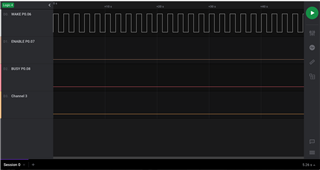
    I have GPIO 6 toggling every second, but nothing on 7 and 8.

  • tscribne said:
    I have GPIO 6 toggling every second, but nothing on 7 and 8.

    I took a look at the nrf52832-mdk schematic, but I did not see any reason for why pin 7 and 8 should not work.

    Unfortunately, I do not have a nrf52832-mdk. Since it's Makerdiary that created this board, I recommend asking about this issue in the Makerdiary community forum: https://community.makerdiary.com/ , or send them a message from this page: https://makerdiary.com/pages/faqs

  • I took your sample and created a test program very similar to yours.  Unfortunately, I am getting the same response as before with P0.06 toggling and P0.07 and P0.08 with no response.  I am using the nrf52dk_nrf52832 dts with slight modifications for my UART

    #include <zephyr.h>
    #include <sys/printk.h>
    #include <stdio.h>
    #include <string.h>
    #include <shell/shell.h>
    #include <shell/shell_uart.h>
    #include <version.h>
    #include <logging/log.h>
    #include <stdlib.h>
    #include <device.h>
    #include <drivers/gpio.h>
    #include <console/console.h>
    
    #define WATCHDOG_STACK_SIZE		500
    #define WATCHDOG_PRIORITY		5
    
    #define WATCHDOG_WAKE			1000
    
    struct device *watchdog_dev;
    
    K_THREAD_STACK_DEFINE( watchdog_stack_area, WATCHDOG_STACK_SIZE );
    struct k_thread watchdog_thread_data;
    k_tid_t	watchdog_tid;								// ThreadID
    
    
    #define PIN_1 6
    #define PIN_2 7
    #define PIN_3 8
    
    static struct device *gpio_dev;
    
    /* 
    ** Function: 		watchdog
    ** Description: 	Actual watchdog thread routine.
    */
    void 
    watchdog( 
    	void *unused1, 
    	void *unused2, 
    	void *unused3 )
    {
    	while (1) {
    		printk("+");	
    		gpio_pin_toggle(gpio_dev,PIN_1);
    		gpio_pin_toggle(gpio_dev,PIN_2);
    		gpio_pin_toggle(gpio_dev,PIN_3);
    		k_sleep( WATCHDOG_WAKE );
    
    	}
    }
    
    /*
    ** Function:		start_watchdog Description: 	Starts the
    ** watchdog routine thread
    */
    int 
    start_watchdog()
    {
    
    	//watchdog_dev = device_get_binding("GPIO_0");
    //
    //	ret = gpio_pin_configure(watchdog_dev, LED_PIN, GPIO_OUTPUT_ACTIVE | FLAGS);
    //	if (ret < 0) {
    //		return(1);
    //	}
    //	gpio_pin_set( watchdog_dev, LED_PIN, (int)false);
    //
    
    	watchdog_tid = k_thread_create(&watchdog_thread_data, 
    								   watchdog_stack_area,
    								   K_THREAD_STACK_SIZEOF( watchdog_stack_area ),
    								   watchdog,
    								   NULL, NULL, NULL,
    								   WATCHDOG_PRIORITY,
    								   0,
    								   K_NO_WAIT );
    
    
    	return(0);
    }
    
    
    /*
    ** Function:		stop_watchdog
    ** Description: 	Stop the watchdog function thread
    */
    int
    stop_watchdog()
    {
    	return(0);
    }
    
    
    void main( void )
    {
    	int err;
    	console_init();
    
    	printk("GPIO Test Program\n");
    
    	gpio_dev = device_get_binding(DT_LABEL(DT_NODELABEL(gpio0)));
    	if (gpio_dev == NULL) {
    		printk("GPIO_0 bind error");
    		return;
    	}
    	
    	
    	err = gpio_pin_configure(gpio_dev, PIN_1,
    				GPIO_OUTPUT | GPIO_OUTPUT_INIT_LOW);	
    	if (err) {
    		printk("PIN_1 config error: %d", err);
    	}
    	
    	err = gpio_pin_configure(gpio_dev, PIN_2,
    				GPIO_OUTPUT | GPIO_OUTPUT_INIT_LOW);	
    	if (err) {
    		printk("PIN_2 config error: %d", err);
    	}
    	
    	err = gpio_pin_configure(gpio_dev, PIN_3,
    				GPIO_OUTPUT | GPIO_OUTPUT_INIT_LOW);	
    	if (err) {
    		printk("PIN_3 config error: %d", err);
    	}
    
    	start_watchdog();
    
    	for(;;)
    	{
    		printk("-");
    		k_sleep(500);
    
    	}
    }

    I am at a loss as to what is happening.  Based on my schematic and all the gathered information, there should be no reason why P0.07 and P0.08 should be unresponsive.

    Tom

Related