This post is older than 2 years and might not be relevant anymore
More Info: Consider searching for newer posts

Unable to toggle GPIO P0.0 or P0.1 with Zephyr

Working with nrf52832_mdk and using basic GPIO functionality, I am unable to toggle the GPIO pins P0.0 or P0.1.   The code I am using is quite simple and I am able to toggle the LED's on a nrf52840_pca10056 when compiled in that environment.  When compiling on with nrf52932_mdk, I expect to see some activity on the pins P0.0 or P0.01 when I specify pin 0 or 1, however, there appears to be no activity.  My code is below:

nt 
gpio_set( 
    int pin, 
    bool set )
{
    int err;
    struct device *dev;

    dev = device_get_binding("GPIO_0");


    gpio_pin_configure( dev, pin, GPIO_OUTPUT_ACTIVE );


    if( verbose == true ){
        if ( set == true ) {
            printk("Set GPIO Pin %d - %d", pin,set);
        }else{
            printk("Clear GPIO Pin %d - %d", pin,set );
        }
    }

    err = gpio_pin_set(dev, pin, set);


    if ( verbose == true ) {
        if (err == 0) {
            printk("SUCCESS\n");
        }else{
            printk("FAILED\n");
        }                      
    }

    return( err );
}

Any clues as to why my pins are not toggles would be greatly appreciated.
Tom

Parents
  • Hi,

    Any clues as to why my pins are not toggles would be greatly appreciated.

     It's most likely used for the 32.768 kHz crystal. See the pin assignments for the nRF52832 here.

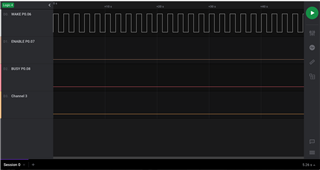
  • Ah, you are correct, I was looking at the wrong schematic.  Anyhow, I'm experiencing the same behavior.  My pins are as follows: 

    P0.06 - Wakeup

    P0.07 - Enable

    P0.08 - BUSY

    P0.11 - RXD

    P0.12 - TXD

    I have normal activity on my RXD/TXD lines and I can communicate clearly with my serial connections, however, whenever I wish to toggle Wakeup, Enable or Busy with the above code I see not electrical activity on my pins (P0.06-07-08).

    Could this be my configuration on my Device Tree for the nrf52832_mdk? 

  • tscribne said:
    Could this be my configuration on my Device Tree for the nrf52832_mdk? 

     Could be. Take a look at the zephyr.dts file in the build_folder/zephyr

  • Yes, I'm looking at my zephyr.dts file and it only includes pins for my UART 11 and 12.

    /dts-v1/;

    / {
    #address-cells = < 0x1 >;
    #size-cells = < 0x1 >;
    model = "nRF52832-MDK Micro Dev Kit";
    compatible = "nrf52832-mdk", "nordic,nrf52832-qfaa", "nordic,nrf52832";
    chosen {
    zephyr,console = &uart0;
    zephyr,shell-uart = &uart0;
    zephyr,uart-mcumgr = &uart0;
    zephyr,bt-mon-uart = &uart0;
    zephyr,bt-c2h-uart = &uart0;
    zephyr,sram = &sram0;
    zephyr,flash = &flash0;
    zephyr,code-partition = &slot0_partition;
    };
    aliases {
    i2c-0 = &i2c0;
    i2c-1 = &i2c1;
    spi-0 = &spi0;
    spi-1 = &spi1;
    spi-2 = &spi2;
    uart-0 = &uart0;
    adc-0 = &adc;
    gpio-0 = &gpio0;
    gpiote-0 = &gpiote;
    wdt-0 = &wdt;
    pwm-0 = &pwm0;
    pwm-1 = &pwm1;
    pwm-2 = &pwm2;
    qdec-0 = &qdec;
    rtc-0 = &rtc0;
    rtc-1 = &rtc1;
    rtc-2 = &rtc2;
    timer-0 = &timer0;
    timer-1 = &timer1;
    timer-2 = &timer2;
    timer-3 = &timer3;
    timer-4 = &timer4;
    };
    soc {
    #address-cells = < 0x1 >;
    #size-cells = < 0x1 >;
    compatible = "nordic,nRF52832-QFAA", "nordic,nRF52832", "nordic,nRF52", "simple-bus";
    interrupt-parent = < &nvic >;
    ranges;
    nvic: interrupt-controller@e000e100 {
    compatible = "arm,v7m-nvic";
    reg = < 0xe000e100 0xc00 >;
    interrupt-controller;
    #interrupt-cells = < 0x2 >;
    arm,num-irq-priority-bits = < 0x3 >;
    phandle = < 0x1 >;
    };
    systick: timer@e000e010 {
    compatible = "arm,armv7m-systick";
    reg = < 0xe000e010 0x10 >;
    status = "disabled";
    };
    flash-controller@4001e000 {
    compatible = "nordic,nrf52-flash-controller";
    reg = < 0x4001e000 0x1000 >;
    #address-cells = < 0x1 >;
    #size-cells = < 0x1 >;
    label = "NRF_FLASH_DRV_NAME";
    flash0: flash@0 {
    compatible = "soc-nv-flash";
    label = "NRF_FLASH";
    erase-block-size = < 0x1000 >;
    write-block-size = < 0x4 >;
    reg = < 0x0 0x80000 >;
    partitions {
    compatible = "fixed-partitions";
    #address-cells = < 0x1 >;
    #size-cells = < 0x1 >;
    boot_partition: partition@0 {
    label = "mcuboot";
    reg = < 0x0 0xc000 >;
    };
    slot0_partition: partition@c000 {
    label = "image-0";
    reg = < 0xc000 0x32000 >;
    };
    slot1_partition: partition@3e000 {
    label = "image-1";
    reg = < 0x3e000 0x32000 >;
    };
    scratch_partition: partition@70000 {
    label = "image-scratch";
    reg = < 0x70000 0xa000 >;
    };
    storage_partition: partition@7a000 {
    label = "storage";
    reg = < 0x7a000 0x6000 >;
    };
    };
    };
    };
    sram0: memory@20000000 {
    compatible = "mmio-sram";
    reg = < 0x20000000 0x10000 >;
    };
    adc: adc@40007000 {
    compatible = "nordic,nrf-saadc";
    reg = < 0x40007000 0x1000 >;
    interrupts = < 0x7 0x1 >;
    status = "disabled";
    label = "ADC_0";
    #io-channel-cells = < 0x1 >;
    };
    clock: clock@40000000 {
    compatible = "nordic,nrf-clock";
    reg = < 0x40000000 0x1000 >;
    interrupts = < 0x0 0x1 >;
    status = "okay";
    label = "CLOCK";
    };
    uart0: uart@40002000 {
    reg = < 0x40002000 0x1000 >;
    interrupts = < 0x2 0x1 >;
    status = "okay";
    label = "UART_0";
    compatible = "nordic,nrf-uart";
    current-speed = < 0x1c200 >;
    tx-pin = < 0xc >;
    rx-pin = < 0xb >;
    };
    gpiote: gpiote@40006000 {
    compatible = "nordic,nrf-gpiote";
    reg = < 0x40006000 0x1000 >;
    interrupts = < 0x6 0x5 >;
    status = "okay";
    label = "GPIOTE_0";
    };
    gpio0: gpio@50000000 {
    compatible = "nordic,nrf-gpio";
    gpio-controller;
    reg = < 0x50000000 0x1000 >;
    #gpio-cells = < 0x2 >;
    label = "GPIO_0";
    status = "okay";
    };
    i2c0: i2c@40003000 {
    #address-cells = < 0x1 >;
    #size-cells = < 0x0 >;
    reg = < 0x40003000 0x1000 >;
    clock-frequency = < 0x186a0 >;
    interrupts = < 0x3 0x1 >;
    status = "disabled";
    label = "I2C_0";
    };
    i2c1: i2c@40004000 {
    #address-cells = < 0x1 >;
    #size-cells = < 0x0 >;
    reg = < 0x40004000 0x1000 >;
    clock-frequency = < 0x186a0 >;
    interrupts = < 0x4 0x1 >;
    status = "disabled";
    label = "I2C_1";
    };
    pwm0: pwm@4001c000 {
    compatible = "nordic,nrf-pwm";
    reg = < 0x4001c000 0x1000 >;
    interrupts = < 0x1c 0x1 >;
    status = "disabled";
    label = "PWM_0";
    #pwm-cells = < 0x1 >;
    };
    pwm1: pwm@40021000 {
    compatible = "nordic,nrf-pwm";
    reg = < 0x40021000 0x1000 >;
    interrupts = < 0x21 0x1 >;
    status = "disabled";
    label = "PWM_1";
    #pwm-cells = < 0x1 >;
    };
    pwm2: pwm@40022000 {
    compatible = "nordic,nrf-pwm";
    reg = < 0x40022000 0x1000 >;
    interrupts = < 0x22 0x1 >;
    status = "disabled";
    label = "PWM_2";
    #pwm-cells = < 0x1 >;
    };
    qdec: qdec@40012000 {
    compatible = "nordic,nrf-qdec";
    reg = < 0x40012000 0x1000 >;
    interrupts = < 0x12 0x1 >;
    status = "disabled";
    label = "QDEC";
    };
    spi0: spi@40003000 {
    #address-cells = < 0x1 >;
    #size-cells = < 0x0 >;
    reg = < 0x40003000 0x1000 >;
    interrupts = < 0x3 0x1 >;
    status = "disabled";
    label = "SPI_0";
    };
    spi1: spi@40004000 {
    #address-cells = < 0x1 >;
    #size-cells = < 0x0 >;
    reg = < 0x40004000 0x1000 >;
    interrupts = < 0x4 0x1 >;
    status = "disabled";
    label = "SPI_1";
    };
    spi2: spi@40023000 {
    #address-cells = < 0x1 >;
    #size-cells = < 0x0 >;
    reg = < 0x40023000 0x1000 >;
    interrupts = < 0x23 0x1 >;
    status = "disabled";
    label = "SPI_2";
    };
    rtc0: rtc@4000b000 {
    compatible = "nordic,nrf-rtc";
    reg = < 0x4000b000 0x1000 >;
    interrupts = < 0xb 0x1 >;
    status = "okay";
    clock-frequency = < 0x8000 >;
    prescaler = < 0x1 >;
    label = "RTC_0";
    };
    rtc1: rtc@40011000 {
    compatible = "nordic,nrf-rtc";
    reg = < 0x40011000 0x1000 >;
    interrupts = < 0x11 0x1 >;
    status = "okay";
    clock-frequency = < 0x8000 >;
    prescaler = < 0x1 >;
    label = "RTC_1";
    };
    rtc2: rtc@40024000 {
    compatible = "nordic,nrf-rtc";
    reg = < 0x40024000 0x1000 >;
    interrupts = < 0x24 0x1 >;
    status = "okay";
    clock-frequency = < 0x8000 >;
    prescaler = < 0x1 >;
    label = "RTC_2";
    };
    timer0: timer@40008000 {
    compatible = "nordic,nrf-timer";
    status = "okay";
    reg = < 0x40008000 0x1000 >;
    interrupts = < 0x8 0x1 >;
    prescaler = < 0x0 >;
    label = "TIMER_0";
    };
    timer1: timer@40009000 {
    compatible = "nordic,nrf-timer";
    status = "okay";
    reg = < 0x40009000 0x1000 >;
    interrupts = < 0x9 0x1 >;
    prescaler = < 0x0 >;
    label = "TIMER_1";
    };
    timer2: timer@4000a000 {
    compatible = "nordic,nrf-timer";
    status = "okay";
    reg = < 0x4000a000 0x1000 >;
    interrupts = < 0xa 0x1 >;
    prescaler = < 0x0 >;
    label = "TIMER_2";
    };
    timer3: timer@4001a000 {
    compatible = "nordic,nrf-timer";
    status = "okay";
    reg = < 0x4001a000 0x1000 >;
    interrupts = < 0x1a 0x1 >;
    prescaler = < 0x0 >;
    label = "TIMER_3";
    };
    timer4: timer@4001b000 {
    compatible = "nordic,nrf-timer";
    status = "okay";
    reg = < 0x4001b000 0x1000 >;
    interrupts = < 0x1b 0x1 >;
    prescaler = < 0x0 >;
    label = "TIMER_4";
    };
    temp: temp@4000c000 {
    compatible = "nordic,nrf-temp";
    reg = < 0x4000c000 0x1000 >;
    interrupts = < 0xc 0x1 >;
    status = "okay";
    label = "TEMP_0";
    };
    wdt: watchdog@40010000 {
    compatible = "nordic,nrf-watchdog";
    reg = < 0x40010000 0x1000 >;
    interrupts = < 0x10 0x1 >;
    status = "okay";
    label = "WDT";
    };
    };
    sw_pwm: sw-pwm {
    compatible = "nordic,nrf-sw-pwm";
    status = "disabled";
    label = "SW_PWM";
    timer-instance = < 0x2 >;
    channel-count = < 0x3 >;
    clock-prescaler = < 0x0 >;
    ppi-base = < 0xe >;
    gpiote-base = < 0x0 >;
    #pwm-cells = < 0x1 >;
    };
    cpus {
    #address-cells = < 0x1 >;
    #size-cells = < 0x0 >;
    cpu@0 {
    device_type = "cpu";
    compatible = "arm,cortex-m4f";
    reg = < 0x0 >;
    };
    };
    };

Reply
  • Yes, I'm looking at my zephyr.dts file and it only includes pins for my UART 11 and 12.

    /dts-v1/;

    / {
    #address-cells = < 0x1 >;
    #size-cells = < 0x1 >;
    model = "nRF52832-MDK Micro Dev Kit";
    compatible = "nrf52832-mdk", "nordic,nrf52832-qfaa", "nordic,nrf52832";
    chosen {
    zephyr,console = &uart0;
    zephyr,shell-uart = &uart0;
    zephyr,uart-mcumgr = &uart0;
    zephyr,bt-mon-uart = &uart0;
    zephyr,bt-c2h-uart = &uart0;
    zephyr,sram = &sram0;
    zephyr,flash = &flash0;
    zephyr,code-partition = &slot0_partition;
    };
    aliases {
    i2c-0 = &i2c0;
    i2c-1 = &i2c1;
    spi-0 = &spi0;
    spi-1 = &spi1;
    spi-2 = &spi2;
    uart-0 = &uart0;
    adc-0 = &adc;
    gpio-0 = &gpio0;
    gpiote-0 = &gpiote;
    wdt-0 = &wdt;
    pwm-0 = &pwm0;
    pwm-1 = &pwm1;
    pwm-2 = &pwm2;
    qdec-0 = &qdec;
    rtc-0 = &rtc0;
    rtc-1 = &rtc1;
    rtc-2 = &rtc2;
    timer-0 = &timer0;
    timer-1 = &timer1;
    timer-2 = &timer2;
    timer-3 = &timer3;
    timer-4 = &timer4;
    };
    soc {
    #address-cells = < 0x1 >;
    #size-cells = < 0x1 >;
    compatible = "nordic,nRF52832-QFAA", "nordic,nRF52832", "nordic,nRF52", "simple-bus";
    interrupt-parent = < &nvic >;
    ranges;
    nvic: interrupt-controller@e000e100 {
    compatible = "arm,v7m-nvic";
    reg = < 0xe000e100 0xc00 >;
    interrupt-controller;
    #interrupt-cells = < 0x2 >;
    arm,num-irq-priority-bits = < 0x3 >;
    phandle = < 0x1 >;
    };
    systick: timer@e000e010 {
    compatible = "arm,armv7m-systick";
    reg = < 0xe000e010 0x10 >;
    status = "disabled";
    };
    flash-controller@4001e000 {
    compatible = "nordic,nrf52-flash-controller";
    reg = < 0x4001e000 0x1000 >;
    #address-cells = < 0x1 >;
    #size-cells = < 0x1 >;
    label = "NRF_FLASH_DRV_NAME";
    flash0: flash@0 {
    compatible = "soc-nv-flash";
    label = "NRF_FLASH";
    erase-block-size = < 0x1000 >;
    write-block-size = < 0x4 >;
    reg = < 0x0 0x80000 >;
    partitions {
    compatible = "fixed-partitions";
    #address-cells = < 0x1 >;
    #size-cells = < 0x1 >;
    boot_partition: partition@0 {
    label = "mcuboot";
    reg = < 0x0 0xc000 >;
    };
    slot0_partition: partition@c000 {
    label = "image-0";
    reg = < 0xc000 0x32000 >;
    };
    slot1_partition: partition@3e000 {
    label = "image-1";
    reg = < 0x3e000 0x32000 >;
    };
    scratch_partition: partition@70000 {
    label = "image-scratch";
    reg = < 0x70000 0xa000 >;
    };
    storage_partition: partition@7a000 {
    label = "storage";
    reg = < 0x7a000 0x6000 >;
    };
    };
    };
    };
    sram0: memory@20000000 {
    compatible = "mmio-sram";
    reg = < 0x20000000 0x10000 >;
    };
    adc: adc@40007000 {
    compatible = "nordic,nrf-saadc";
    reg = < 0x40007000 0x1000 >;
    interrupts = < 0x7 0x1 >;
    status = "disabled";
    label = "ADC_0";
    #io-channel-cells = < 0x1 >;
    };
    clock: clock@40000000 {
    compatible = "nordic,nrf-clock";
    reg = < 0x40000000 0x1000 >;
    interrupts = < 0x0 0x1 >;
    status = "okay";
    label = "CLOCK";
    };
    uart0: uart@40002000 {
    reg = < 0x40002000 0x1000 >;
    interrupts = < 0x2 0x1 >;
    status = "okay";
    label = "UART_0";
    compatible = "nordic,nrf-uart";
    current-speed = < 0x1c200 >;
    tx-pin = < 0xc >;
    rx-pin = < 0xb >;
    };
    gpiote: gpiote@40006000 {
    compatible = "nordic,nrf-gpiote";
    reg = < 0x40006000 0x1000 >;
    interrupts = < 0x6 0x5 >;
    status = "okay";
    label = "GPIOTE_0";
    };
    gpio0: gpio@50000000 {
    compatible = "nordic,nrf-gpio";
    gpio-controller;
    reg = < 0x50000000 0x1000 >;
    #gpio-cells = < 0x2 >;
    label = "GPIO_0";
    status = "okay";
    };
    i2c0: i2c@40003000 {
    #address-cells = < 0x1 >;
    #size-cells = < 0x0 >;
    reg = < 0x40003000 0x1000 >;
    clock-frequency = < 0x186a0 >;
    interrupts = < 0x3 0x1 >;
    status = "disabled";
    label = "I2C_0";
    };
    i2c1: i2c@40004000 {
    #address-cells = < 0x1 >;
    #size-cells = < 0x0 >;
    reg = < 0x40004000 0x1000 >;
    clock-frequency = < 0x186a0 >;
    interrupts = < 0x4 0x1 >;
    status = "disabled";
    label = "I2C_1";
    };
    pwm0: pwm@4001c000 {
    compatible = "nordic,nrf-pwm";
    reg = < 0x4001c000 0x1000 >;
    interrupts = < 0x1c 0x1 >;
    status = "disabled";
    label = "PWM_0";
    #pwm-cells = < 0x1 >;
    };
    pwm1: pwm@40021000 {
    compatible = "nordic,nrf-pwm";
    reg = < 0x40021000 0x1000 >;
    interrupts = < 0x21 0x1 >;
    status = "disabled";
    label = "PWM_1";
    #pwm-cells = < 0x1 >;
    };
    pwm2: pwm@40022000 {
    compatible = "nordic,nrf-pwm";
    reg = < 0x40022000 0x1000 >;
    interrupts = < 0x22 0x1 >;
    status = "disabled";
    label = "PWM_2";
    #pwm-cells = < 0x1 >;
    };
    qdec: qdec@40012000 {
    compatible = "nordic,nrf-qdec";
    reg = < 0x40012000 0x1000 >;
    interrupts = < 0x12 0x1 >;
    status = "disabled";
    label = "QDEC";
    };
    spi0: spi@40003000 {
    #address-cells = < 0x1 >;
    #size-cells = < 0x0 >;
    reg = < 0x40003000 0x1000 >;
    interrupts = < 0x3 0x1 >;
    status = "disabled";
    label = "SPI_0";
    };
    spi1: spi@40004000 {
    #address-cells = < 0x1 >;
    #size-cells = < 0x0 >;
    reg = < 0x40004000 0x1000 >;
    interrupts = < 0x4 0x1 >;
    status = "disabled";
    label = "SPI_1";
    };
    spi2: spi@40023000 {
    #address-cells = < 0x1 >;
    #size-cells = < 0x0 >;
    reg = < 0x40023000 0x1000 >;
    interrupts = < 0x23 0x1 >;
    status = "disabled";
    label = "SPI_2";
    };
    rtc0: rtc@4000b000 {
    compatible = "nordic,nrf-rtc";
    reg = < 0x4000b000 0x1000 >;
    interrupts = < 0xb 0x1 >;
    status = "okay";
    clock-frequency = < 0x8000 >;
    prescaler = < 0x1 >;
    label = "RTC_0";
    };
    rtc1: rtc@40011000 {
    compatible = "nordic,nrf-rtc";
    reg = < 0x40011000 0x1000 >;
    interrupts = < 0x11 0x1 >;
    status = "okay";
    clock-frequency = < 0x8000 >;
    prescaler = < 0x1 >;
    label = "RTC_1";
    };
    rtc2: rtc@40024000 {
    compatible = "nordic,nrf-rtc";
    reg = < 0x40024000 0x1000 >;
    interrupts = < 0x24 0x1 >;
    status = "okay";
    clock-frequency = < 0x8000 >;
    prescaler = < 0x1 >;
    label = "RTC_2";
    };
    timer0: timer@40008000 {
    compatible = "nordic,nrf-timer";
    status = "okay";
    reg = < 0x40008000 0x1000 >;
    interrupts = < 0x8 0x1 >;
    prescaler = < 0x0 >;
    label = "TIMER_0";
    };
    timer1: timer@40009000 {
    compatible = "nordic,nrf-timer";
    status = "okay";
    reg = < 0x40009000 0x1000 >;
    interrupts = < 0x9 0x1 >;
    prescaler = < 0x0 >;
    label = "TIMER_1";
    };
    timer2: timer@4000a000 {
    compatible = "nordic,nrf-timer";
    status = "okay";
    reg = < 0x4000a000 0x1000 >;
    interrupts = < 0xa 0x1 >;
    prescaler = < 0x0 >;
    label = "TIMER_2";
    };
    timer3: timer@4001a000 {
    compatible = "nordic,nrf-timer";
    status = "okay";
    reg = < 0x4001a000 0x1000 >;
    interrupts = < 0x1a 0x1 >;
    prescaler = < 0x0 >;
    label = "TIMER_3";
    };
    timer4: timer@4001b000 {
    compatible = "nordic,nrf-timer";
    status = "okay";
    reg = < 0x4001b000 0x1000 >;
    interrupts = < 0x1b 0x1 >;
    prescaler = < 0x0 >;
    label = "TIMER_4";
    };
    temp: temp@4000c000 {
    compatible = "nordic,nrf-temp";
    reg = < 0x4000c000 0x1000 >;
    interrupts = < 0xc 0x1 >;
    status = "okay";
    label = "TEMP_0";
    };
    wdt: watchdog@40010000 {
    compatible = "nordic,nrf-watchdog";
    reg = < 0x40010000 0x1000 >;
    interrupts = < 0x10 0x1 >;
    status = "okay";
    label = "WDT";
    };
    };
    sw_pwm: sw-pwm {
    compatible = "nordic,nrf-sw-pwm";
    status = "disabled";
    label = "SW_PWM";
    timer-instance = < 0x2 >;
    channel-count = < 0x3 >;
    clock-prescaler = < 0x0 >;
    ppi-base = < 0xe >;
    gpiote-base = < 0x0 >;
    #pwm-cells = < 0x1 >;
    };
    cpus {
    #address-cells = < 0x1 >;
    #size-cells = < 0x0 >;
    cpu@0 {
    device_type = "cpu";
    compatible = "arm,cortex-m4f";
    reg = < 0x0 >;
    };
    };
    };

Children
  • Try building and running this program on your board:

    gpio_test.zip

    It should toggle pin 6,7 and 8 every second.

  • Interesting,

    I tried your program, had to make modifications in the following.

    CMakeLists.txt

    #
    # Copyright (c) 2020 Nordic Semiconductor
    #
    # SPDX-License-Identifier: LicenseRef-BSD-5-Clause-Nordic
    #

    cmake_minimum_required(VERSION 3.8.2)

    set(NRF_SUPPORTED_BOARDS
    nrf5340pdk_nrf5340_cpunet
    nrf52dk_nrf52832
    nrf52840dk_nrf52840
    )

    #find_package(Zephyr REQUIRED HINTS $ENV{ZEPHYR_BASE})

    include($ENV{ZEPHYR_BASE}/cmake/app/boilerplate.cmake NO_POLICY_SCOPE)
    project(peripheral_dis)

    FILE(GLOB app_sources src/*.c)
    target_sources(app PRIVATE
    ${app_sources}
    )

    and in main.c

    gpio_dev = device_get_binding("GPIO_0" ); //DT_LABEL(DT_NODELABEL(gpio0)));
    if (gpio_dev == NULL) {
    printk("GPIO_0 bind error");
    return;
    }

    I have GPIO 6 toggling every second, but nothing on 7 and 8.

  • tscribne said:
    I have GPIO 6 toggling every second, but nothing on 7 and 8.

    I took a look at the nrf52832-mdk schematic, but I did not see any reason for why pin 7 and 8 should not work.

    Unfortunately, I do not have a nrf52832-mdk. Since it's Makerdiary that created this board, I recommend asking about this issue in the Makerdiary community forum: https://community.makerdiary.com/ , or send them a message from this page: https://makerdiary.com/pages/faqs

  • I took your sample and created a test program very similar to yours.  Unfortunately, I am getting the same response as before with P0.06 toggling and P0.07 and P0.08 with no response.  I am using the nrf52dk_nrf52832 dts with slight modifications for my UART

    #include <zephyr.h>
    #include <sys/printk.h>
    #include <stdio.h>
    #include <string.h>
    #include <shell/shell.h>
    #include <shell/shell_uart.h>
    #include <version.h>
    #include <logging/log.h>
    #include <stdlib.h>
    #include <device.h>
    #include <drivers/gpio.h>
    #include <console/console.h>
    
    #define WATCHDOG_STACK_SIZE		500
    #define WATCHDOG_PRIORITY		5
    
    #define WATCHDOG_WAKE			1000
    
    struct device *watchdog_dev;
    
    K_THREAD_STACK_DEFINE( watchdog_stack_area, WATCHDOG_STACK_SIZE );
    struct k_thread watchdog_thread_data;
    k_tid_t	watchdog_tid;								// ThreadID
    
    
    #define PIN_1 6
    #define PIN_2 7
    #define PIN_3 8
    
    static struct device *gpio_dev;
    
    /* 
    ** Function: 		watchdog
    ** Description: 	Actual watchdog thread routine.
    */
    void 
    watchdog( 
    	void *unused1, 
    	void *unused2, 
    	void *unused3 )
    {
    	while (1) {
    		printk("+");	
    		gpio_pin_toggle(gpio_dev,PIN_1);
    		gpio_pin_toggle(gpio_dev,PIN_2);
    		gpio_pin_toggle(gpio_dev,PIN_3);
    		k_sleep( WATCHDOG_WAKE );
    
    	}
    }
    
    /*
    ** Function:		start_watchdog Description: 	Starts the
    ** watchdog routine thread
    */
    int 
    start_watchdog()
    {
    
    	//watchdog_dev = device_get_binding("GPIO_0");
    //
    //	ret = gpio_pin_configure(watchdog_dev, LED_PIN, GPIO_OUTPUT_ACTIVE | FLAGS);
    //	if (ret < 0) {
    //		return(1);
    //	}
    //	gpio_pin_set( watchdog_dev, LED_PIN, (int)false);
    //
    
    	watchdog_tid = k_thread_create(&watchdog_thread_data, 
    								   watchdog_stack_area,
    								   K_THREAD_STACK_SIZEOF( watchdog_stack_area ),
    								   watchdog,
    								   NULL, NULL, NULL,
    								   WATCHDOG_PRIORITY,
    								   0,
    								   K_NO_WAIT );
    
    
    	return(0);
    }
    
    
    /*
    ** Function:		stop_watchdog
    ** Description: 	Stop the watchdog function thread
    */
    int
    stop_watchdog()
    {
    	return(0);
    }
    
    
    void main( void )
    {
    	int err;
    	console_init();
    
    	printk("GPIO Test Program\n");
    
    	gpio_dev = device_get_binding(DT_LABEL(DT_NODELABEL(gpio0)));
    	if (gpio_dev == NULL) {
    		printk("GPIO_0 bind error");
    		return;
    	}
    	
    	
    	err = gpio_pin_configure(gpio_dev, PIN_1,
    				GPIO_OUTPUT | GPIO_OUTPUT_INIT_LOW);	
    	if (err) {
    		printk("PIN_1 config error: %d", err);
    	}
    	
    	err = gpio_pin_configure(gpio_dev, PIN_2,
    				GPIO_OUTPUT | GPIO_OUTPUT_INIT_LOW);	
    	if (err) {
    		printk("PIN_2 config error: %d", err);
    	}
    	
    	err = gpio_pin_configure(gpio_dev, PIN_3,
    				GPIO_OUTPUT | GPIO_OUTPUT_INIT_LOW);	
    	if (err) {
    		printk("PIN_3 config error: %d", err);
    	}
    
    	start_watchdog();
    
    	for(;;)
    	{
    		printk("-");
    		k_sleep(500);
    
    	}
    }

    I am at a loss as to what is happening.  Based on my schematic and all the gathered information, there should be no reason why P0.07 and P0.08 should be unresponsive.

    Tom

  • It's a long shot, but you could you try to print the values of UART RTS and CTS pins, and see if 7 and 8 is printed. If not, it might be a HW issue with this board.

        printk("Value of NRF_UART0->PSELCTS: %d \n",NRF_UART0->PSELCTS);
    	printk("Value of NRF_UART0->PSELRTS: %d \n",NRF_UART0->PSELRTS);

Related