This post is older than 2 years and might not be relevant anymore
More Info: Consider searching for newer posts

NRF52840 Dongle: How to save as file after read the files in NRF CONNECT?

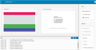
Hi I am able to choose the nrf 52840 dongle in NRF Connect . However, compared to nrf 52840 DK , I am able to  read then save as file/ erase & write / erase all.

With this dongle , Im not able to do so . Please advice how do I read and save as file.Thank you so much.


Parents
  • Hello,

    Unfortunately, it is not possible to read out the firmware of the dongle, simply because it doesn't have an programming chip, like the DK has. If you want to read the FW you need to attach a debugger to the P1 connectors beneath the dongle, and then use an external debugger (e.g. the nRF52840 DK, or any other DK from Nordic) and  use that to read out the flash.

    BR,
    Edvin

  • Hi Edvin, 

    If I have nRF52840 DK to be the external debugger, should I program the DK first? And which firmware / example should I flash into the DK before it can be use as external debugger to help read the DONGLE flash?

    Kindly state the steps possible?

    Thank you .

    Regards,

    Kathleen

  • Hello Kathleen,

    You don't need to program anything specific on the DK. The only thing you need to use is the debug out port on the DK, which is located in the top left corner of the DK, marked with P19. On the dongle, you have two options:

    1: You can solder on a10 pin segger header, and use a 10 pin segger cable (only the last picture on this article) to the P1 connector marked "1" in the picture,

    2: You can use a 10 pin needle adapter and push it against the square marked "2" on the picture.

    Please read this guide carefully before you choose to program anything using the debug port on the dongle.

    May I ask why you need to read out the FW on the dongle? You probably flashed it yourself at some point? 

    When you connect the DEBUG OUT (P19) on the DK to the debug ports on the dongle (which needs to be powered), the programmer/debugger on the DK will detect that something else is connected to the debugger, and it will use this connected device as the target instead of the nRF on the DK itself. 

    Please note that the P20 pins on the DK can also be used for debugging on external devices. For an explanation on how to do that, please check out this post. Please note that VTG and GND_DETECT doesn't provide GND and VDD, but rather use it to detect whether or not an external device is connected or not. This is not that relevant for the dongle, because the programming pins are only reachable through the connectors 1 and 2 in the above picture. 

    Best regards,

    Edvin

Reply
  • Hello Kathleen,

    You don't need to program anything specific on the DK. The only thing you need to use is the debug out port on the DK, which is located in the top left corner of the DK, marked with P19. On the dongle, you have two options:

    1: You can solder on a10 pin segger header, and use a 10 pin segger cable (only the last picture on this article) to the P1 connector marked "1" in the picture,

    2: You can use a 10 pin needle adapter and push it against the square marked "2" on the picture.

    Please read this guide carefully before you choose to program anything using the debug port on the dongle.

    May I ask why you need to read out the FW on the dongle? You probably flashed it yourself at some point? 

    When you connect the DEBUG OUT (P19) on the DK to the debug ports on the dongle (which needs to be powered), the programmer/debugger on the DK will detect that something else is connected to the debugger, and it will use this connected device as the target instead of the nRF on the DK itself. 

    Please note that the P20 pins on the DK can also be used for debugging on external devices. For an explanation on how to do that, please check out this post. Please note that VTG and GND_DETECT doesn't provide GND and VDD, but rather use it to detect whether or not an external device is connected or not. This is not that relevant for the dongle, because the programming pins are only reachable through the connectors 1 and 2 in the above picture. 

    Best regards,

    Edvin

Children
No Data
Related