This post is older than 2 years and might not be relevant anymore
More Info: Consider searching for newer posts

TWI on nRF51822

I just entered a Case to Nordic with this same question but do not expect to get a response over the weekend so I am posting here. I made the assumption that the Nordic Cases and the Developer Zone are not related. If this is considered a double-post I apologize.

I used the RF6350_radio_configuration_example as a starting point for our TWI interface. The goal is for the nRF51822 to act a a Master and send commands to a Slave to read/write the Slave's RAM/EEPROM.

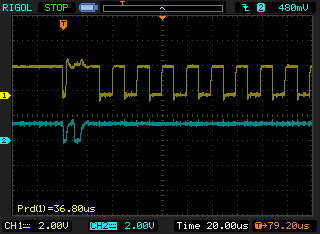
I am using the nRF51822 EK with our TWI Slave attached and uVision 4 and the TWI transmission are unsuccessful. When a command is issured there are two negative SDA pulses followed by continuous SCL pulses. (36 usec period = 27.8KHz). The Slave requires clock freuencies of 10KHz-100KHz. When the code reaches “if (timeout == 0)” in the twi_master_write() while loop timeout always equals 0 which may be why the transmissioin fails. Of course this may not be the only problem.

I am still plugging away on this but time is short so any suggestions will be appreciated.

twi.txt

Parents
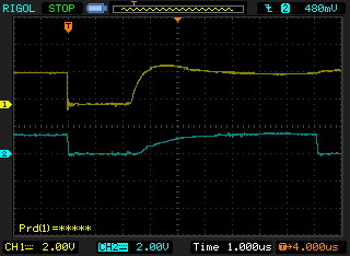
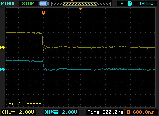
  • Attached are the SCL (yellow) and SDA (blue) waveforms. The difference between the 3 traces is the timebase.

    After starting SCL runs continuously. SDA looks completely wrong so there is something major wrong. The slow risetime of SDA implies there may not be a pullup but I have enabled the on-chip pullups (none external) for SCL and SDA. I appears that both SCL and SDA go low nearly simultaneously (much less than 20ns apart).

    I misunderstood youe question and uploaded the nRF51822 rather than the slave device. I thought that was an unusual request. :)

    This forum is very particular about what file types can be attached. I attached the waveforms in BMP format and apparently they are not allowed. Here they are after converting to JPG.

    SDA-SCL 1.jpg

    SDA-SCL 2.jpg

    SDA-SCL 3.jpg

    MLX90325.pdf

Reply
  • Attached are the SCL (yellow) and SDA (blue) waveforms. The difference between the 3 traces is the timebase.

    After starting SCL runs continuously. SDA looks completely wrong so there is something major wrong. The slow risetime of SDA implies there may not be a pullup but I have enabled the on-chip pullups (none external) for SCL and SDA. I appears that both SCL and SDA go low nearly simultaneously (much less than 20ns apart).

    I misunderstood youe question and uploaded the nRF51822 rather than the slave device. I thought that was an unusual request. :)

    This forum is very particular about what file types can be attached. I attached the waveforms in BMP format and apparently they are not allowed. Here they are after converting to JPG.

    SDA-SCL 1.jpg

    SDA-SCL 2.jpg

    SDA-SCL 3.jpg

    MLX90325.pdf

Children
No Data
Related