This post is older than 2 years and might not be relevant anymore
More Info: Consider searching for newer posts

TWI on nRF51822

I just entered a Case to Nordic with this same question but do not expect to get a response over the weekend so I am posting here. I made the assumption that the Nordic Cases and the Developer Zone are not related. If this is considered a double-post I apologize.

I used the RF6350_radio_configuration_example as a starting point for our TWI interface. The goal is for the nRF51822 to act a a Master and send commands to a Slave to read/write the Slave's RAM/EEPROM.

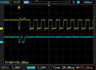
I am using the nRF51822 EK with our TWI Slave attached and uVision 4 and the TWI transmission are unsuccessful. When a command is issured there are two negative SDA pulses followed by continuous SCL pulses. (36 usec period = 27.8KHz). The Slave requires clock freuencies of 10KHz-100KHz. When the code reaches “if (timeout == 0)” in the twi_master_write() while loop timeout always equals 0 which may be why the transmissioin fails. Of course this may not be the only problem.

I am still plugging away on this but time is short so any suggestions will be appreciated.

twi.txt

  • Hi Tom,

    Are you able to share the datasheet of the device you're working with?

    Also, it sounds like you have a logic analyzer hooked-up (which is a Good Thing(tm)) -- are you seeing SCL go low after SDA goes low? i.e. an I2C/TWI start sequence?

    The timing and pattern is important, so you'll want to capture both synchronously if you can.

    See the attached image URL for details.

    I'll go through your code, but I'm also experimenting with I2C, so may not be much help :p

    Cheers,

    -m

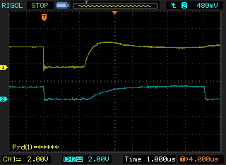
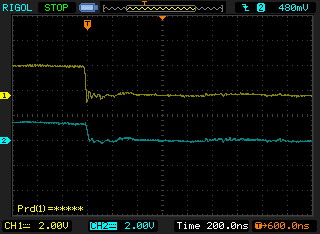
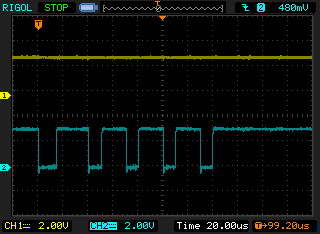
  • Attached are the SCL (yellow) and SDA (blue) waveforms. The difference between the 3 traces is the timebase.

    After starting SCL runs continuously. SDA looks completely wrong so there is something major wrong. The slow risetime of SDA implies there may not be a pullup but I have enabled the on-chip pullups (none external) for SCL and SDA. I appears that both SCL and SDA go low nearly simultaneously (much less than 20ns apart).

    I misunderstood youe question and uploaded the nRF51822 rather than the slave device. I thought that was an unusual request. :)

    This forum is very particular about what file types can be attached. I attached the waveforms in BMP format and apparently they are not allowed. Here they are after converting to JPG.

    SDA-SCL 1.jpg

    SDA-SCL 2.jpg

    SDA-SCL 3.jpg

    MLX90325.pdf

  • I can see the problem: your waveforms look exactly like the nRF51822 data sheet!

    (I think you attached the wrong file...)

    -m

  • Hi Tom

    What is the supply to your system? From the graphs you sent, the SDA line goes to about 2.4V while the CLK only rises to about 1.3V. According to the datasheet of your TWI device, you need a supply of at least 2.6V and that comms should go up to 2.5V. Comms will definitely not work. Will you also send the pin configuration of your TWI lines? I do not see them in the code. Please note that according to Figure 15 in the nrf51822 Ref Manual, it appears that the pull configuration is only used when the pin has the input buffer enabled. Not sure if the pull-up is used when configured as output? Have you connected two external resistors to your comms lines to see if you can at least get comms to work to your device first? Maybe give this a try if you have not yet.

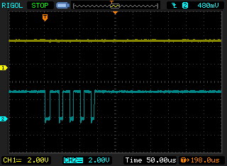
  • Attached are the latest waveforms and revised code showing port initialization. I found a wiring error to the sensor (no power) but still is not working. Apparently the TX is not completing because it always exits the following command in twi_master_write() with timeout = 0. Five CLK's are issued but no SDA.

    while(NRF_TWI1->EVENTS_TXDSENT == 0 && (--timeout)); // HANGING HERE (TIMEOUT ALWAYS 0)

    SDA-SCL 4.jpg

    SDA-SCL 5.jpg

    twi.txt

Related