This post is older than 2 years and might not be relevant anymore
More Info: Consider searching for newer posts

Custom Board configuration

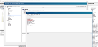
I am trying to make the custom_board.h header file but I have some questions. I am using the PCA10040.h as a starting point. However I am confused on some of the things included for in that file

1. What's LED_START, LED_STOP and is that necessary?

2. Same for Buttons

3. What is the difference between SER_APP_RX_PIN and RX_PIN_NUMBER and SER_CON_RX_PIN? They all are  UART pins so I am carious why 3 different definitions

4. I need a chip disable signal and I2C for my board, I have defined them starting from line 58 to 63, is it done properly?

5. How do I call this header file in the c file? Is it #include "custom_board.h" first in the boards.h file and that way #include bsh.h would work in the c file or do I need to do something different?

#ifndef CUSTOM_BOARD_H
#define CUSTOM_BOARD_H

#ifdef __cplusplus
extern "C" {
#endif

#include "nrf_gpio.h"

// LEDs definitions for custom_board
#define LEDS_NUMBER    4

#define LED_START      25
#define LED_1          25
#define LED_2          26
#define LED_3          27
#define LED_STOP       27

#define LEDS_ACTIVE_STATE 0

#define LEDS_INV_MASK  LEDS_MASK

#define LEDS_LIST { LED_1, LED_2, LED_3 }

#define BSP_LED_0      LED_1
#define BSP_LED_1      LED_2
#define BSP_LED_2      LED_3

#define BUTTONS_NUMBER 1

#define BUTTON_START   24
#define BUTTON_1       24
#define BUTTON_STOP    24
#define BUTTON_PULL    NRF_GPIO_PIN_PULLUP

#define BUTTONS_ACTIVE_STATE 0

#define BUTTONS_LIST { BUTTON_1 }

#define BSP_BUTTON_0   BUTTON_1


#define RX_PIN_NUMBER  8
#define TX_PIN_NUMBER  6

#define HWFC           false

// serialization APPLICATION board - temp. setup for running serialized MEMU tests
#define SER_APP_RX_PIN              8    // UART RX pin number.
#define SER_APP_TX_PIN              6    // UART TX pin number.

// serialization CONNECTIVITY board
#define SER_CON_RX_PIN              8    // UART RX pin number.
#define SER_CON_TX_PIN              6    // UART TX pin number.

#define SER_CONN_CHIP_RESET_PIN     18    // Pin used to reset connectivity chip

// Chip disable signal for another chip 
#define CD_n                        20

//I2C interface pin definition
#define SCL_PIN                     15
#define SDA_PIN                     17

#ifdef __cplusplus
}
#endif

#endif // PCA10040_H

Parents
  • Hi.

    If you're using nRF52840 then PCA10056 would be the better option to base your custom board file on. 

    1. Just an "alias" for LED1 and LED 4, not necessary.
    2. Depends on your project. If you're going to use an example from the SDK that uses the buttons then yes it's necessary. If not, then no.
    3. Used internally in some of the serialization files.
    4. The SWD pins on the nRF52 are not optional. It has dedicated pins for this. Use the same as in the PCA10056 board file.
    5.  Correct. You only need to define custom_board.


  • 3. The RX Pins for the different definitions is different, should I keep this exactly like it was?

    4. I don't see any SWD pin assignment in the PCA10056 header file. Also, the signals I mentioned in OP are custom signal connected to corresponding pins, I wanted to know if they were configured properly.

    5. Right, I am confused where I have to define this and take out PCA10056 being defined since I am using the example from the SDK to make the project?

Reply
  • 3. The RX Pins for the different definitions is different, should I keep this exactly like it was?

    4. I don't see any SWD pin assignment in the PCA10056 header file. Also, the signals I mentioned in OP are custom signal connected to corresponding pins, I wanted to know if they were configured properly.

    5. Right, I am confused where I have to define this and take out PCA10056 being defined since I am using the example from the SDK to make the project?

Children
  • 3. You can keep them as in the PCA10056 board file

    4.  Sorry, this was entirely my fault, I glanced a bit too quick on the board file. Forget my previous point, just make sure that the I2C pins are assigned to the left or under side of the chip as the pins on the right side and upper side of the IC are marked as low frequency/low drive in the product specification.

    5. This is usually done as part of the pre-processor defines. I've included a snippet from SES, if you use GCC then it's done in the bottom of the makefile.

Related