This post is older than 2 years and might not be relevant anymore
More Info: Consider searching for newer posts

BLE beacon 2.4GHz PCB antenna layout for SoC Nordic nRF52832

Schematic, suggested by the datasheet:

PCB is round with 33mm, FR4 1.6mm

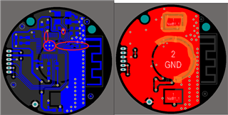
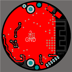
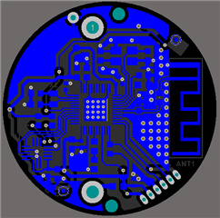
Bottom side

Top side

Bottom+top

3d view

How about the question on the last picture? It is better to keep the solder mask open or close it? If open, which PCB surface finish is better? Tin, Nickel, Gold ENIG?

I wonder if my ground plane is ok, do you see something that could change on it in order to obtain good results with the antenna? I followed the spacing between antenna and ground according to AN043 drawings.

And also, you can see on schematic that there is an inductor in series (3.9nH) an a capacitor (0.8pF) to ground on the RF line. RF line is 8 mils width, with 8mils isolation to ground. I wonder if these values are the best to use as starting point. Can calculate them correctly? I'm not from RF area.

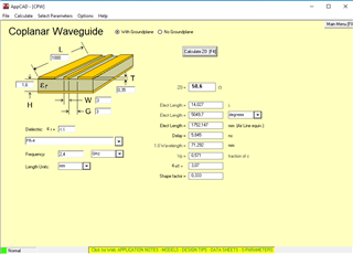
As said, PCB trace of RF line (4mm lenght only) is 8 mils width, 8 mils clearance to ground (coplanar waveguide). If an internal ground plane layer on the PCB is used, and between these 2 layers we have 0.18mm clearance, the RF line will have 50 ohms, I know this because I already used this before for other boards. So I wonder if I can make the PCB with only 2 layers and dont take care about the impedance that it will have in practice, because the trace lenght is only 4mm.

Regards,

Jeferson.

  • Hi Jeferson,

    could you upload the gerber files? Then it's easier for me to give you a proper review.

    Best regards,
    Kaja

  • Hi Kaja.
    Thanks.

    Here we go: https://www.mediafire.com/file/wluo0dp0qz23hm1/PCB_BN1_B_Gerbers.zip/file

    It is also included the Altium layout file (PcbDoc extension).

    The PCB layout was changed since creation of topic. I have added a LIS3DHTR accelerometer.
    But regarding the ground plane, it did not changed.

    Regards,

    Jeferson

  • Hi Jeferson,

    here is the feedback:

    1. Due to errata 138 you need capacitors, C = 12 pF, on P0.25 and P0.26. Or if the pin's are unused you can use the alternative workaround: ground the pin's.
    2. You need to correct the RF path, the reference design should be directly copied from the reference design, grounding of C3, placement of the components, the track after L1 should be a 50 Ohm transmission line. 
    3. The antenna needs a pi-network for impedance matching. 
    4. The ground layer is to fragmented, under the RF path all the way to under the center pad i should be solid ground, to create a RF shield. 
    5. The grounding of one of the crystal pad's and capacitor is not god, make sure the ground layer is connected. 
    6. Ground the center pad via VSS pin 45. 
    7. The center pad should be grounded with 4*4 via hole. 
    8. The solder mask on top of the antenna, does not matter if you have or not, and type does not matter, it affects the antenna minimal. 


    Best regards,
    Kaja

  • Hi Kaja. Thanks.

    1. Due to errata 138 you need capacitors, C = 12 pF, on P0.25 and P0.26. Or if the pin's are unused you can use the alternative workaround: ground the pin's.

    Ok. P0.25 and P0.26 are now connected to GND.

    2. You need to correct the RF path, the reference design should be directly copied from the reference design, grounding of C3, placement of the components, the track after L1 should be a 50 Ohm transmission line.

    Yes, the trace has 50 omhs, and I changed the placement of capacitors of crystal.

    3. The antenna needs a pi-network for impedance matching.

    I followed the schematic circuit. Is there a capacitor missing in my board? If yes, connected from where to where?


    4. The ground layer is to fragmented, under the RF path all the way to under the center pad i should be solid ground, to create a RF shield.

    Under the RF path there is solid ground. Changed the ground plane of top layer (red color).


    5. The grounding of one of the crystal pad's and capacitor is not god, make sure the ground layer is connected.

    Changed this part.

    6. Ground the center pad via VSS pin 45.

    Changed.


    7. The center pad should be grounded with 4*4 via hole.

    Ok. Changed.

    8. The solder mask on top of the antenna, does not matter if you have or not, and type does not matter, it affects the antenna minimal.

    I did removed the solder mask openings on the antenna.


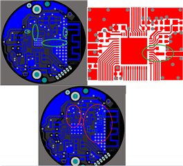
    New printscreens:

    Did the layout improved?


    If you need the Gerbers, you can download here:
    www.mediafire.com/.../file


    Regards,
    Jeferson.

  • Hi Jeferson,

    I tried to illustrate 1, 2, 3, 6 and 7 better.
    Please check the footprint of the center pad. 

    The antenna need a pi-network, as I illustrated over. The two components you already have is to match the output impedance of the radio. 

    Find the right width and distance to ground for the trace between the radio matching network antenna antenna, so that it's 50 Ohm:


    Best regards,
    Kaja

Related