This post is older than 2 years and might not be relevant anymore
More Info: Consider searching for newer posts

Programming/debugging external custom nRF52840 boards using nRF52840 DK

Hi All,

I came across this thread regarding programming external boards. (https://devzone.nordicsemi.com/f/nordic-q-a/14058/external-programming-using-nrf52-dk)

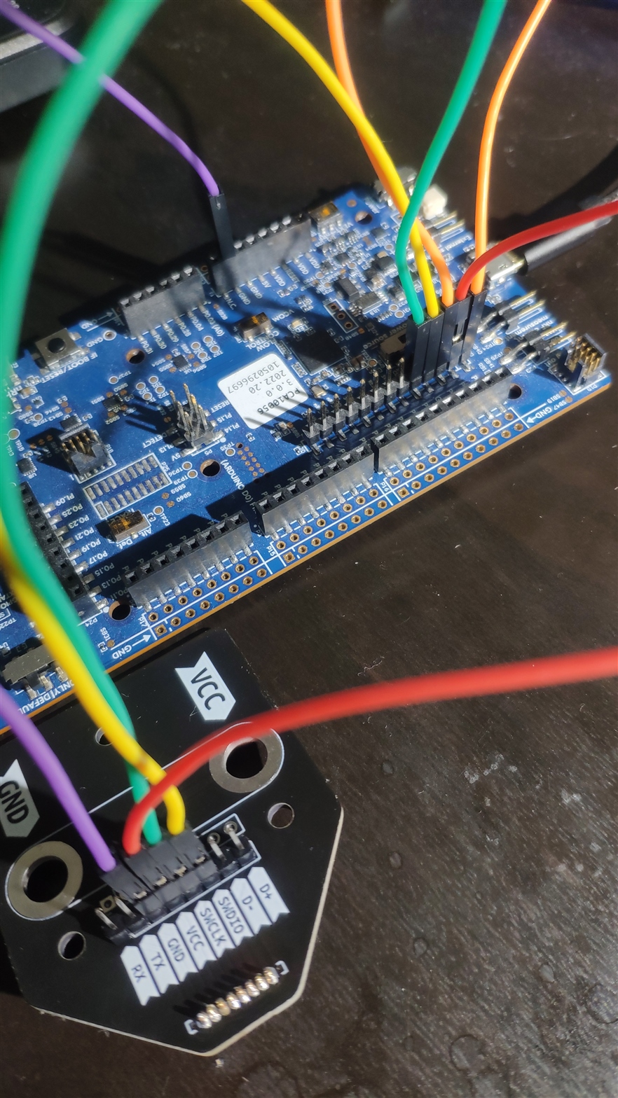
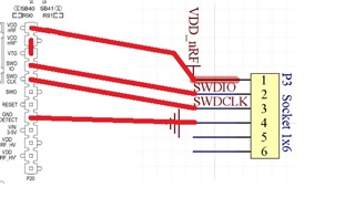
In order to program my external board using my DK, I am going to use the following setup as described in the above link. "P3 Socket" is in my external circuit.

1. Is there any other modifications need to be done to the DK if I am using the nRF52840 DK to program external circuits?

2. In my design, VDD_nRF in the DK is connected to the VDD_nRF in the external board. In this case should I remove external board battery as well? Can I also power up my external board this way?

3. If I am to debug my board using Segger Embedded Studio, can I use the above connection directly?

4. If I use the above connection, how does it affect the current nRF52840 chip in the DK? Should disable any connections to this chip in the DK?

5. The "RESET" in the DK, should I directly connect to the RESET pin in the external board? Is it necessary to have it?

6. Why does it named as GND_DETECT in the DK instead of just GND?

  • Hi!

    Have you solved your problem with flashing MS88SF2? 
    I have exactly the same problem. I'm using nrf52840dk revision 3.0.0 and the P20 connector has different labels than connector mentioned in the first post. 

    The connector has:
    VDD nrf

    VDD nrf

    SWD SEL

    SWD IO

    SWD CLK

    SWO

    RESET

    empty

    VIN 3-5v

    VDD nRF_HV

    VDD nRF_HV'

    VIO REF

    empty

    Does anybody know how to connect external board with nrf52840 (MS88SF2) to flash it, please?

    Thank you

  • Hi, were you able to resolve this issue. Neither my nrf52dk has a GND Detect pin

  • Hi Simonr. Can you suggest me what I can do in case my NRF52DK does not have GND DETECT pin

  • Hi, yes I solved it. The newer version (the one with nrf53 as a programmer) doesn't use common GND to detect external board is connected. They use common VDD instead. You can see my connection in the image below.

    The orange wire is connected from VDD to SWD SEL (to select external board).

    My problem was, that I probably used damaged development kit (the LED 5 was not blinking or shining). I tried to use another one and then it worked!

    Hope it solves your problem as well. 

  • Perfect! now it seems to be communicating. Thank you so much.

1 2 3