This post is older than 2 years and might not be relevant anymore
More Info: Consider searching for newer posts

ADC channel reading values when connected to ground

Hi,

Hope you are doing good.

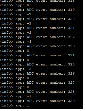
I run the SAADC signal to from the sdk and observed that  when the adc input is connected to ground, the adc reads few random negative value( reference image attached below). is this a common behavior when the analog input is connected to ground?How do i correct this so that i do not make any measurement errors?

Thank-you

Warm Regards

Harini Krisha

Parents
  • Hi,

    This is due to noise and offset error. Do a calibration and see if it helps. 

    regards

    Jared 

  • Dear Jared,

    there are some particular procedure to doing that or simply collect some value, get the mean value and then use it as offset?

    Thanks and best regards.

    F.

  • Hi,

    How often you should call the calibration routine depends on how often the temperature will change. If you don't expect any temperature change then it's enough to do it once at the start.

    I've updated my previous answer with the correct URL. See the example for a reference on how to implement it. 

    regards

    Jared

  • Hi Jared, thanks, I've succesfully implemented the calibration steps thanks, of course I still get negative value when the input is directly wired to the 0V and as I'm reading through the forum I'm clipping every negative value to 0.

    I'm just curious how the offset calibration work, I think is done completely inside the ADC module by disconnecting the ADC input from the external pin of the chip, I'm right?

    Thanks and best regards.

    F.

  • Hi,

    We do not share information regarding the details of the internal calibration routine. What you might be observing is ground bounce. Have you tried using differential mode, and connecting the second pin directly to the GND of the source that you're measuring? 

    I think it's best that you create a new case for discussing your issues. 

    regards

    Jared 

  • Dear Jared,

    I'm not asking about the internal code used to perform the calibration, just know if this offset calibration is done internally the chip by electronically disconnect the input pin of the ADC, so is not requested any external action by me, or if to perform the calibration I've to ground externally the ADC pin. Of course, in this last scenario, this is not practicable in a real usage because the input is connected to the sensor where the signal have to be read and doing such things make the circuit more complicated, hence is mainly for this reason I've asked in what way is done the calibration, then kindly note not need to know detail about the code used to perform this task, but essentially from an hardware point of view, sorry if I've not specifiede better in my previous request.

    Thanks and best regards.

    F.

  • Hi,

    STE said:
    just know if this offset calibration is done internally the chip by electronically disconnect the input pin of the ADC, so is not requested any external action by me, or if to perform the calibration I've to ground externally the ADC pin.

    No external action is needed for the calibration routine to complete. Which means that you don't have to modify the circuit externally. 

    best regards

    Jared

Reply
  • Hi,

    STE said:
    just know if this offset calibration is done internally the chip by electronically disconnect the input pin of the ADC, so is not requested any external action by me, or if to perform the calibration I've to ground externally the ADC pin.

    No external action is needed for the calibration routine to complete. Which means that you don't have to modify the circuit externally. 

    best regards

    Jared

Children
Related