This post is older than 2 years and might not be relevant anymore
More Info: Consider searching for newer posts

nRF24L01+ Antenna and Board Design

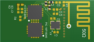
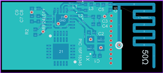
I would like to tightly integrate a nRF24L01+ with my microcontroller. I have read as much as I could, and copied as closely as I can, but the best layout required moving components from the examples. I tried to move components I thought might be less sensitive to being moved... I would love to get a more experienced opinion before I run boards. Any feedback is appreciated. Thanks!

Instead of multiple via's separating the antenna from circuit would it be better to cut a slot to more thoroughly separate the antenna or do the via's add something?

0402 components throughout. 

FA-20H 16.0000MF12Z-AC3 oscillator

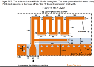
I got the antenna design from: https://www.cypress.com/file/136236/download page 10

I plan to run boards from JLCPCB: JLCPCB specs
Parents Reply
  • choose ​Murata Crystal​ XRCGB16M000FXN00R0​, which I think meets the specs, however when I calculate C1/C2 I get a value of about 10pF. I expected to get a value closer to the reference Cap value: 22pF. I think the lower Cap value is because the 6pF Crystal CL is  relatively low, but I want to make sure I've got it right.

    Did I do something wrong here or does this look ok?​   -Thanks!

    ​Ccap = 6pf * 2 - (~1.5pf)​ = 10.5pf
    XRCGB16M000FXN00R0
    Manufacturer:​ ​​​Murata
    Load Capacitance:​ ​6 pF
    Frequency:​ ​16 MHz
    Tolerance:​ ​40 PPM
    Frequency Stability:​ ​25 PPM, 30 PPM
    ESR:​ ​200 Ohms
    Drive Level:​ ​100 uW
Children
  • The value of the load capacitors are dependent only of the CL value of the crystal. 22 pF caps are for a 12 pF crystal. 

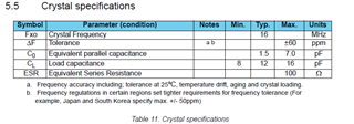
    You can find the crystal spec in the datasheet: 

    Note that ESR should be less than 100 ohm. And min CL is 8 pF, sorry for saying 6 - 7 pF earlier. 

    This excludes the smallest packages as ESR will increase when the crystal gets physically smaller. 

Related