This post is older than 2 years and might not be relevant anymore
More Info: Consider searching for newer posts

Reading more than events with GPIOTE using high accuracy?

I'm using SDK 15.2

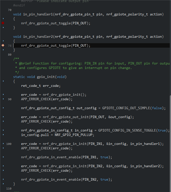
I'm trying to read two separate events configure in two separate pins (PIN_1 and PIN_2) with two different handlers (handler_1 and handler_2), like this:

if (!nrf_drv_gpiote_is_init()) {
err_code = nrf_drv_gpiote_init();
}

APP_ERROR_CHECK(err_code);

nrf_drv_gpiote_in_config_t in_config = GPIOTE_CONFIG_IN_SENSE_HITOLO(true);
in_config.pull = NRF_GPIO_PIN_PULLUP;

const auto err_code = nrf_drv_gpiote_in_init(PIN_1, &in_config, handler_1);

APP_ERROR_CHECK(err_code);

nrf_drv_gpiote_in_event_enable(PIN_1, true);

const auto err_code = nrf_drv_gpiote_in_init(PIN_2, &in_config, handler_2);

APP_ERROR_CHECK(err_code);

nrf_drv_gpiote_in_event_enable(PIN_2, true);


But in that way, only the event that was configured first works. In other words, if the event for PIN_1 is configured first it works, but just that event.
If event for PIN_2 is configured first it works, but just that event.

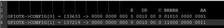
When I was debugging I've found out that nrfx_gpiote_irq_handler is not even called for the event that was configured last, so it might be some configuration problem

Am I missing something here?

Thanks!

Parents
  • Hi Jose,

    I have verified that this works just fine with the pin_int_change example in the SDK. I added another IN pin configuration to match your use case and i can see that the second pin handler is called as you can see from the snapshot where the breakpoint is being hit.

    My guess is that you are verifying this in the debugger by building your code in release mode and due to max code optimizations, the debugger thinks that your handler2 code is not being used.

    I suggest you test this by compiling your code with debug settings with no code optimizations.

    Attaching you the C file i tested this with.

    /**
     * Copyright (c) 2014 - 2020, Nordic Semiconductor ASA
     *
     * All rights reserved.
     *
     * Redistribution and use in source and binary forms, with or without modification,
     * are permitted provided that the following conditions are met:
     *
     * 1. Redistributions of source code must retain the above copyright notice, this
     *    list of conditions and the following disclaimer.
     *
     * 2. Redistributions in binary form, except as embedded into a Nordic
     *    Semiconductor ASA integrated circuit in a product or a software update for
     *    such product, must reproduce the above copyright notice, this list of
     *    conditions and the following disclaimer in the documentation and/or other
     *    materials provided with the distribution.
     *
     * 3. Neither the name of Nordic Semiconductor ASA nor the names of its
     *    contributors may be used to endorse or promote products derived from this
     *    software without specific prior written permission.
     *
     * 4. This software, with or without modification, must only be used with a
     *    Nordic Semiconductor ASA integrated circuit.
     *
     * 5. Any software provided in binary form under this license must not be reverse
     *    engineered, decompiled, modified and/or disassembled.
     *
     * THIS SOFTWARE IS PROVIDED BY NORDIC SEMICONDUCTOR ASA "AS IS" AND ANY EXPRESS
     * OR IMPLIED WARRANTIES, INCLUDING, BUT NOT LIMITED TO, THE IMPLIED WARRANTIES
     * OF MERCHANTABILITY, NONINFRINGEMENT, AND FITNESS FOR A PARTICULAR PURPOSE ARE
     * DISCLAIMED. IN NO EVENT SHALL NORDIC SEMICONDUCTOR ASA OR CONTRIBUTORS BE
     * LIABLE FOR ANY DIRECT, INDIRECT, INCIDENTAL, SPECIAL, EXEMPLARY, OR
     * CONSEQUENTIAL DAMAGES (INCLUDING, BUT NOT LIMITED TO, PROCUREMENT OF SUBSTITUTE
     * GOODS OR SERVICES; LOSS OF USE, DATA, OR PROFITS; OR BUSINESS INTERRUPTION)
     * HOWEVER CAUSED AND ON ANY THEORY OF LIABILITY, WHETHER IN CONTRACT, STRICT
     * LIABILITY, OR TORT (INCLUDING NEGLIGENCE OR OTHERWISE) ARISING IN ANY WAY OUT
     * OF THE USE OF THIS SOFTWARE, EVEN IF ADVISED OF THE POSSIBILITY OF SUCH DAMAGE.
     *
     */
    /** @file
     * @defgroup pin_change_int_example_main main.c
     * @{
     * @ingroup pin_change_int_example
     * @brief Pin Change Interrupt Example Application main file.
     *
     * This file contains the source code for a sample application using interrupts triggered by GPIO pins.
     *
     */
    
    #include <stdbool.h>
    #include "nrf.h"
    #include "nrf_drv_gpiote.h"
    #include "app_error.h"
    #include "boards.h"
    
    #ifdef BSP_BUTTON_0
        #define PIN_IN1 BSP_BUTTON_0
        #define PIN_IN2 BSP_BUTTON_1
    #endif
    #ifndef PIN_IN1
        #error "Please indicate input pin"
    #endif
    
    #ifdef BSP_LED_0
        #define PIN_OUT BSP_LED_0
    #endif
    #ifndef PIN_OUT
        #error "Please indicate output pin"
    #endif
    
    void in_pin_handler1(nrf_drv_gpiote_pin_t pin, nrf_gpiote_polarity_t action)
    {
        nrf_drv_gpiote_out_toggle(PIN_OUT);
    }
    
    void in_pin_handler2(nrf_drv_gpiote_pin_t pin, nrf_gpiote_polarity_t action)
    {
        nrf_drv_gpiote_out_toggle(PIN_OUT);
    }
    
    /**
     * @brief Function for configuring: PIN_IN pin for input, PIN_OUT pin for output,
     * and configures GPIOTE to give an interrupt on pin change.
     */
    static void gpio_init(void)
    {
        ret_code_t err_code;
    
        err_code = nrf_drv_gpiote_init();
        APP_ERROR_CHECK(err_code);
    
        nrf_drv_gpiote_out_config_t out_config = GPIOTE_CONFIG_OUT_SIMPLE(false);
    
        err_code = nrf_drv_gpiote_out_init(PIN_OUT, &out_config);
        APP_ERROR_CHECK(err_code);
    
        nrf_drv_gpiote_in_config_t in_config = GPIOTE_CONFIG_IN_SENSE_TOGGLE(true);
        in_config.pull = NRF_GPIO_PIN_PULLUP;
    
        err_code = nrf_drv_gpiote_in_init(PIN_IN1, &in_config, in_pin_handler1);
        APP_ERROR_CHECK(err_code);
    
        nrf_drv_gpiote_in_event_enable(PIN_IN1, true);
    
        err_code = nrf_drv_gpiote_in_init(PIN_IN2, &in_config, in_pin_handler2);
        APP_ERROR_CHECK(err_code);
    
        nrf_drv_gpiote_in_event_enable(PIN_IN2, true);
    }
    
    /**
     * @brief Function for application main entry.
     */
    int main(void)
    {
        gpio_init();
    
        while (true)
        {
            // Do nothing.
        }
    }
    
    
    /** @} */
    

  • The actual code is not exactly the same because it is already integrated into our codebase, so the calls to these statements are in different files because they are setting up different features, but logic-wise they are doing the same operations.
    I turned off all the optimizations and it's still not working, the bit fields in the register CONFIG[1] are still incorrect, as Kyle pointed out. Looks like that when we call "nrf_drv_gpiote_in_init" more than one time it messes up the configuration of the GPIOTE peripheral, and in our case, we can see this by checking that the MODE field in the CONFIG register is being changed to Task for some reason when it should be Event.

    I'm copying and pasting the configuration being done in the first file:

    ret_code_t err_code = 0;
    
    if (!nrf_drv_gpiote_is_init()) {
        err_code = nrf_drv_gpiote_init();
    }
    
    APP_ERROR_CHECK(err_code);
    
    nrf_drv_gpiote_in_config_t in_config = GPIOTE_CONFIG_IN_SENSE_HITOLO(true);
    in_config.pull = NRF_GPIO_PIN_PULLUP;
    
    err_code = nrf_drv_gpiote_in_init(PIN_1, &in_config, reset_button_handler);
    APP_ERROR_CHECK(err_code);
    
    nrf_drv_gpiote_in_event_enable(PIN_1, true);
    

    And in the second file we have:

      ret_code_t err_code = 0;
    
        if (!nrf_drv_gpiote_is_init()) {
            err_code = nrf_drv_gpiote_init();
        }
    
        APP_ERROR_CHECK(err_code);
    
        nrf_drv_gpiote_in_config_t in_config = GPIOTE_CONFIG_IN_SENSE_HITOLO(true);
        in_config.pull = NRF_GPIO_PIN_PULLUP;
    
        const auto err_code2 = nrf_drv_gpiote_in_init(PIN_2, &in_config, wiznet_IRQ_handler);
    
        APP_ERROR_CHECK(err_code2);
    
        nrf_drv_gpiote_in_event_enable(PIN_2, true);

    I copied and pasted the code, so this is the code that's actually being executed, the only difference is that they are on different source files in the project.

  • More info, right after all the configuration is done, I'm printing the values of the registers of the GPIOTE peripheral. Here's what I got:

    GPIOTE->CONFIG[0] = 133633 -> 0000 0000 000 0 0010 00 0 01010 0000 0001
    GPIOTE->CONFIG[1] = 137219 -> 0000 0000 000 0 0010 00 0 11000 0000 0011

    And a picture with the fields highlighted:


    So, the only difference between then are the B fields which indicates the PIN and the A fields which indicates the mode. The event associated with CONFIG[1] register is not working, and that's probably because the Mode field is set to Task (11) for some reason.

    After all the configuration is done, if I add the following line of code:

    NRF_GPIOTE->CONFIG[1] &= 0xFFFFFFFD;

    This forces the bit at position 1 to be zero, while not changing any of the other bits.
    And then everything works fine after that.

    Any feedback? Thanks!

Reply
  • More info, right after all the configuration is done, I'm printing the values of the registers of the GPIOTE peripheral. Here's what I got:

    GPIOTE->CONFIG[0] = 133633 -> 0000 0000 000 0 0010 00 0 01010 0000 0001
    GPIOTE->CONFIG[1] = 137219 -> 0000 0000 000 0 0010 00 0 11000 0000 0011

    And a picture with the fields highlighted:


    So, the only difference between then are the B fields which indicates the PIN and the A fields which indicates the mode. The event associated with CONFIG[1] register is not working, and that's probably because the Mode field is set to Task (11) for some reason.

    After all the configuration is done, if I add the following line of code:

    NRF_GPIOTE->CONFIG[1] &= 0xFFFFFFFD;

    This forces the bit at position 1 to be zero, while not changing any of the other bits.
    And then everything works fine after that.

    Any feedback? Thanks!

Children
  • One more info. I commented out the first configuration part in the first source file in my project and copied your code to the second configuration part in the second source file, and ran into the same issue, the MODE field in the CONFIG[1] register is being set to TASK for some reason. Here's the code:

            ret_code_t err_code = 0;
           
            err_code = nrf_drv_gpiote_init();
    
            APP_ERROR_CHECK(err_code);
    
            nrf_drv_gpiote_in_config_t in_config = GPIOTE_CONFIG_IN_SENSE_TOGGLE(true);
            in_config.pull = NRF_GPIO_PIN_PULLUP;
    
            err_code = nrf_drv_gpiote_in_init(PIN_1, &in_config, in_pin_handler1);
            APP_ERROR_CHECK(err_code);
    
            nrf_drv_gpiote_in_event_enable(PIN_1, true);
    
            err_code = nrf_drv_gpiote_in_init(PIN_2, &in_config, in_pin_handler2);
            APP_ERROR_CHECK(err_code);
    
            nrf_drv_gpiote_in_event_enable(PIN_2, true);
    
            for (auto i = 0; i < 2; i++) {
                Log("[%d] = %d", i, NRF_GPIOTE->CONFIG[i]);    
            }

    And the values I've read from the registers after the Log call at the end:

    GPIOTE->CONFIG[0] = 199169 -> 0000 0000 000 0 0011 00 0 01010 0000 0001
    GPIOTE->CONFIG[1] = 202755 -> 0000 0000 000 0 0011 00 0 11000 0000 0011

  • Sorry guys, that was our own code that was changing the GPIOTE peripheral to task mode
    There's a legacy code that we are using that configures the peripheral manually, without using the SDK, and it was hardcoded to use the GPIOTE channel 1, that's why it was being changed everytime to task mode

Related