This post is older than 2 years and might not be relevant anymore
More Info: Consider searching for newer posts

Use libuarte example with GPIO

Good afternoon everyone,

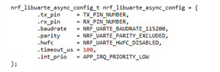
I am facing problems using libuarte example (SDK 17 and NRF52 DK. Using SES and S132, PCA 10040)
It works well with puTTY or other software, but I want to use it to read data from an Arduino.

What I do is the following : 
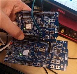
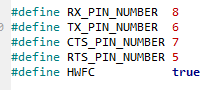
I connect the RX pin to pin 8 and TX pin to pin 6 as described in the pca10040.h.
Rx is connected to the Tx pin of my Arduino (which is sending data, I can see it with the blinking LED), but I do not see any LED on with the NRF52 DK nor any response ... 

From what I've understood, whenever the nrf52 receives data, it must echo it, but it does not echo neither in Arduino, neither in puTTY. (I've understood that I need to use NRF_LOG_INFO to print using puTTY because UART was used with GPIO)

I've also tried the uart project, using flow Control, but I've been unable to receive data as well ...

Is there something that need to be changed in the example to read data with UART using the RX pin and libuarte example ?

Thanks a lot for your answer,

Roduss

Parents
  • Hi Roduss

    The example should work fine as long as the UART signals are routed correctly, and the voltage levels are compatible. 

    Are you saying you don't even get the echoing to work even when using the DK alone, without connecting any external boards?

    One thing to keep in mind when connecting an external UART is that pins 6 and 8 already have a connection to the programming chip on the DK, which is how it gets connected to the virtual J-Link comport. When connecting to an external board you might have to change to some other pins, or break the SB22, SB23, SB24 and SB25 solder bridges to break the connection between the programming chip and the nRF52832. 

    Best regards
    Torbjørn

  • Good afternoon,
    Thanks for your quick answer !
    If I use the DK alone, I get the echo via puTTY, this is working.
    What I want is to send a signal using UART protocol with my Arduino (5V) and receive it with the DK. (And when I receive data, print it to puTTY or make a LED blinking)
    The Arduino can send a start bit/ a stop bit or even Flow Control if necessary.

    So, when you're saying
    UART is that pins 6 and 8 already have a connection to the programming chip on the DK, which is how it gets connected to the virtual J-Link comport

    Is this related to  ?

    So, a solution to make the libuarte example work could be :

    • Connect the Tx of the Arduino to a random pin of the DK (let's say pin 20 will be RX)
    • Connect the Rx of the Arduino to another pin of the DK (pin 21 will be TX)
    • Change anything of this function (or the definition of the RX/TX pins picture above) to initialize pin 20 and 21 as RX and TX? (function is from main.c)
    • Change anything to see the data being echoed in puTTY when received ?

    Thanks a lot for your help !

  • Hi 

    If your Arduino board is running at 5V it won't be compatible with the nRF52DK, which typically runs at ~3V. 

    You would need some kind of level shifter on the UART signals: Either by using a dedicated level shifter IC, or making something more simple based on the fact that the signals are one directional (a 5V to 3V level shifter might be implemented by a simple voltage divider, while 3V to 5V could be implemented with some transistors). 

    Best regards
    Torbjørn

  • Hi,

    Ooops my bad ! So I changed my wiring to send 3.3V to the nRF DK, but still, I don't get the fundamentals ...
    How should I wire my RX/TX with the DK to see data from Arduino ?

    As you said, pin 6 and 8 are used, so I tried to use pin 11 & 12 (TX and RX), initialize them like this : 

    #define TX_PIN 11 
    #define RX_PIN 12
    
    void gpio_init(void)
    {
      nrf_gpio_cfg_input(RX_PIN, NRF_GPIO_PIN_NOPULL);
      nrf_gpio_cfg_output(TX_PIN);
    }

    And used them in the libuarte config function  :

    nrf_libuarte_async_config_t nrf_libuarte_async_config = {
                .tx_pin     = TX_PIN,
                .rx_pin     = RX_PIN,
                .baudrate   = NRF_UARTE_BAUDRATE_115200,
                .parity     = NRF_UARTE_PARITY_EXCLUDED,
                .hwfc       = NRF_UARTE_HWFC_DISABLED,
                .timeout_us = 100,
                .int_prio   = APP_IRQ_PRIORITY_LOW
        };


    But didn't read nothing ...
    What am I missing ? Should I use another example ? 

  • Hi 

    There is no need to manually call the nrf_gpio_cfg_xxx functions when using libuarte. When you enable the UART the pin configuration will be overridden by the UART module. 

    I was able to move the TX and RX to pin 11 and 12 simply by changing the .tx_pin and .rx_pin defines in the libuarte config struct. 

    I tested it just to be sure, by connecting pin 11 and 12 on one kit to pin 6 and 8 on another kit (in order to connect these pins to a PC through the Segger chip on the second kit). 

    Are you still having issues with it?

    Best regards
    Torbjørn

  • Hi,
    Thanks a lot for your answer, I'll have a look at it this week and tell you more about it soon, but it sounds good !
    Best regards

Reply Children
  • No problem, just let me know when you have more questions Slight smile

  • Hellooo,
    I tried your solution, copied a brand new example, changed my libuarte config, connected it to the Arduino and it finally worked !
    It was that simple finally ....
    I still had some transmission issues with baudrate at 115200 and 38400, it works really good at 9600, but I think it might more be an echo problem from the Arduino and the AltSoftSerial/SoftwareSerial libraries, so my issue is solved !

    Do you confirm that you have perfect transmission using 2 nRF kits at 115200 bps ?

    One last thing I would like to be sure about, is libuarte  supposed to be more accurate than the UART example without Flow control ? (I ended up using the UART example withtout using the flow control and I didn't get any transmissions errors)

  • Hi

    One thing you can try if you're having transmission problems is to enable the external HF clock constantly from your application. 

    Using external HF clock means you will have much more accurate baudrate generation for the UART. Without it you could have as much as +/- 5% drift on the clock, which could lead to bit errors over the UART. 

    If you're not using a SoftDevice then enabling external HF clock can be done as easy as this:

    NRF_CLOCK->TASKS_HFCLKSTART = 1;

    roduss said:
    Do you confirm that you have perfect transmission using 2 nRF kits at 115200 bps ?

    Yes, if you're using external HF clock like I mentioned above. 

    roduss said:
    One last thing I would like to be sure about, is libuarte  supposed to be more accurate than the UART example without Flow control ? (I ended up using the UART example withtout using the flow control and I didn't get any transmissions errors)

    I won't say libuarte is more accurate, but it is more flexible if you have a UART application where you are receiving data at random times, and where you don't know how much data you will receive ahead of time. 

    With the older UART driver you have to wait until the RX buffer fills up before you receive any data, which can take a lot of time if you have a large buffer. 

    With the libuarte driver you can define a timeout period, and if no more data is received for this long you will get whatever data is currently in the buffer. 

    Best regards
    Torbjørn

Related