This post is older than 2 years and might not be relevant anymore
More Info: Consider searching for newer posts

SPI simultaneous transfers

Dear all,

Pushing the hardware to the limits, I came up with a question about the architecture of the microcontroller itself: Can two different instances of SPIM start a transfer EXACTLY at the same time?
(Not just work simultaneously like in https://devzone.nordicsemi.com/f/nordic-q-a/29760/nrf52840-spi-simultaneous-connection).

Description:
I am using a single nRF52840-DK, running to instances of SPIM: SPIM 1 and SPIM 2 at the same time.
SPIM 1 is triggered by the compare event of TIMER 1 and a PPI channel connects them both.
SPIM 2 is triggered in the callback function of TIMER 2, no PPI channels involved.

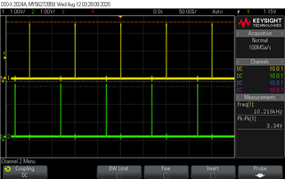
When I trigger TIMER 1 and 2 at 100 us, it works fine, like in the following picture. The pulses are the CLK signal of each SPIM, 16 bits each. I am quite sure the interrupts are generated at the same time but one is delayed due to the other one's priority, but that's good enough.

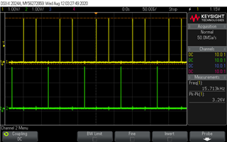
But ideally I would like TIMER 1 to tick every 100 us and TIMER 2 every 50 or 25 us. When I change that (SPIM 2 being the yellow trace), it looks like this, SPIM 2 triggering whenever SPIM 1 allows.

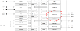
Since there are four possible instances of SPIM, I had the idea they would work independently, but checking the Product Specification (https://infocenter.nordicsemi.com/pdf/nRF52840_OPS_v0.5.pdf, page 12), the block diagram shows only one physical SPIM peripheral:

In a nutshell: Is it somehow possible to start more than one SPIM transfer at the same time (if so, how?), or only one SPIM transfer can be started because they share the same physical peripheral? Or another explanation?

Best regards,

Fran89

Parents
  • An SPIM instance is a part of a serial peripheral unit(UART/SPI/TWI), of which there 4 (I believe) with different UART/SPI/TWI capabilities. This means that you can have up to 4 SPIM instances running independently, though you will then not have access to any UART or TWI instances. 

    There might be a limitation to running two SPIM instances at the exact same time and that is the EasyDMA bus, see Memory and EasyDMA.
    As the two SPIM peripheral's will act as bus masters, and each RAM block is controlled by one slave, you might get a wait-state as the EasyDMA slave can only serve one master at a time. I assume this wait state does not exceed one 16MHz clock cycle (PCKL16M). ie one of your SPIM transfers might get delayed by 62.5ns.

    If that's a problem then you can place the buffers for each SPIM peripheral in separate RAM blocks, then you should not have any DMA collisions. 

  • Thanks for the answer. So I take from it that it is essentially possible to make them run together, those are good news.

    I will take a look at those links you sent, but as for now, the delay between transfers is around 37 us instead of 62.5 ns (which would be tolerable). I just realized the images don't have a enough resolution to see that.

    I will try placing the buffers in separate RAM blocks, and get back to you if the delay disappears.


    Bests,

    Fran

  • Why don't you use the same TIMER event to trigger both SPIM1 and 2 via their TASKS_START (no interrupts), then you can measure it properly.

  • I just finished doing this but implementing two PPI channels instead, one for each SPIM.
    I must admit now I can achieve resolutions of 5 us and both transfers can be started at the same time (but for a few ns) in free-run.

    The problem is when I use the callback function of the timer to update the buffer, apparently that introduces that delay, any timing less than 100 us destabilizes the synchrony.

    But I cannot think of a workaround since that SPIM controls a DAC and I need to change the buffers and time at which I trigger the SPI transfer dynamically.

    EDIT: I am currently checking if that delay can be avoided with direct access to the registers.

Reply
  • I just finished doing this but implementing two PPI channels instead, one for each SPIM.
    I must admit now I can achieve resolutions of 5 us and both transfers can be started at the same time (but for a few ns) in free-run.

    The problem is when I use the callback function of the timer to update the buffer, apparently that introduces that delay, any timing less than 100 us destabilizes the synchrony.

    But I cannot think of a workaround since that SPIM controls a DAC and I need to change the buffers and time at which I trigger the SPI transfer dynamically.

    EDIT: I am currently checking if that delay can be avoided with direct access to the registers.

Children
  • The buffer registers are double-buffered! You can update those register immediately after you get the STARTED event and connect the END event to the START task with the SHORTS register. As long as you update the buffer registers before after the STARTED event and before the next END event, you have a partially free-running SPIM. 

    Alternatively, you can use the EasyDMA array list feature. 
    By enabling the list feature in RXD.LIST, the RXD.PTR and TXD.PTR registers are automatically incremented by the values in their .MAXCOUNT registers. By using the SHORTS register you then have a fully free-running SPIM that will fill up RAM indefinitely. This also means that you need to stop the SPIM at some point or you will overflow. 

    You can count the END events with the CPU and stop the SPIM manually, or, If you have a TIMER and PPI channels to spare, you can count the number of SPIM END events you've received by connecting the END event to the TIMER COUNT task, and trigger the SPIM STOP task on a TIMER COMPARE event. That lets you set an arbitrary number of buffers to fill and then automatically stop the SPIM. 

    This should keep the synchronicity fairly stable as it is not dependent on CPU activity at all. You can also use the TIMER COMPARE events to wake up the CPU after x END events to start processing the data if necessary. 

    In this scenario, you can disable the END event's interrupt as you don't need it anymore, in fact, most of the driver becomes redundant when using the DMA list feature and you're better off just using the HAL to create you own SPIM driver as the current driver is not really suited to hard real-time requirements compared to what can be achieved with the HAL and DMA list. 

    Also, If you need to sample the DAC at a given interval you do not use the END-START shortcut, but use a free-running TIMER to trigger both SPIM transfers. 

    Fran89 said:
    I just finished doing this but implementing two PPI channels instead, one for each SPIM.

     I suggest you rather use one PPI channel and 'fork' the event to a second task (SPIM START), this might reduce the latency between the two SPIMs. See nrfx_ppi_channel_fork_assign

  • Hi,

    First of all, thanks for your help, I solved my problem.

    When accessing the registers directly I meant the TIMER peripheral registers. Using the example's timer initialization plus callback function was very inefficient and the cause of the delay. That was an unknown I had had since the beginning of last year. Luckily I found in the forum someone who implemented them writing the registers directly. The delay has been reduced and I have achieved a 1 us resolution, which if more than enough for what I need.

    But while it works now, I am not completely sure how they are working. Where should I refer to next time when I want to learn how to use the peripherals more in detail? The infocenter is more like a reference manual and the examples are inefficient in terms of resources, I have found this forum more useful. I totally agree making my own driver using the HAL would be the most efficient.

    Best regards,

  • The nRF52840 Product Specification is crucial. It will define how a given peripheral operates, f.ex SPIM — Serial peripheral interface master with EasyDMA. It's important to read both the operational description as well as the register description, as the registers are the interface that is used to control the peripheral. 
    You can also read the given driver source file as an implementation example, but drivers usually leave out some of the functionality that is exposed by the register interface. 

    In the end, the PPI peripheral gives you so many options that it's not feasible to document and create examples for a handful. 

    You can for instance stream SPIM data directly to the RADIO peripheral and out onto the air, just by using a few PPI channels and EasyDMA.
    If you read the peripheral documentation and its register description while knowing that any EVENT can be connected to any TASK, you will discover all sorts of state-machines that can be implemented in HW. 

  • That last application is ultimately what I want to do, thanks for the heads up.

    I will check the link and eventually open another thread if I need help for the implementation.

    Thanks a lot,

    Fran89

Related