This post is older than 2 years and might not be relevant anymore
More Info: Consider searching for newer posts

NRF51822 spi slave and receiving multiple bytes

 Hello,

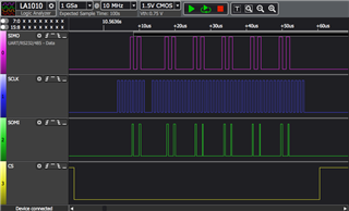
I'm trying to interface msp430fr5994  to nrf51822 as spi slave with soft device 110 and SDK v10. The master (msp40) sends 20 bytes to the slave (nrf51). The issue is that the salve (nrf51) is not receiving anything when I check "NRF_DRV_SPIS_XFER_DONE".  I set up the master spi clock to 1MHz, spi mode, and the bit order to be the same on both (master and slave).  Also, I I at the beginning of the transmission, I used 7500 ns delay after driving the CS low and then starting the *** in the master. At the end of the transmission, I stoped the master clock and delay for 2400ns before driving CS high.   I checked spi_init on the nrf and it seems to be set properly. I'm really struggling to get it the spi to work. what did I miss?

Here is nrf code:

#define TX_BUF_SIZE   20u              /**< SPI TX buffer size. */
#define RX_BUF_SIZE   TX_BUF_SIZE       /**< SPI RX buffer size. */


static volatile bool receiving_completed = false; /**< A flag to inform about completed receiving. */


static nrf_drv_spis_t const m_spis = NRF_DRV_SPIS_INSTANCE(SPIS_INSTANCE_NUMBER);

static uint8_t m_tx_buf[TX_BUF_SIZE];   /**< SPI TX buffer. */
static uint8_t m_rx_buf[RX_BUF_SIZE];   /**< SPI RX buffer. */


/**@brief Function for application main entry.
 */
int main(void)
{

      uint32_t err_code;

    err_code = spi_slave_init();
    APP_ERROR_CHECK(err_code);


    // Enter main loop.
    while(1)
    {
       
        if (receiving_completed)
        {
            
            receiving_completed =false;


            //Set buffers to recevied new data
            err_code = nrf_drv_spis_buffers_set(&m_spis, m_tx_buf, sizeof(m_tx_buf), m_rx_buf, sizeof(m_rx_buf));
            APP_ERROR_CHECK(err_code);
        }
    }
}

uint32_t spi_slave_init(void)
{
    uint32_t              err_code;
    nrf_drv_spis_config_t spis_config = NRF_DRV_SPIS_DEFAULT_CONFIG(SPIS_INSTANCE_NUMBER);

    spis_config.miso_pin        = SPIS_MISO_PIN;
    spis_config.mosi_pin        = SPIS_MOSI_PIN;
    spis_config.sck_pin         = SPIS_SCLK_PIN;
    spis_config.csn_pin         = SPIS_CS_PIN;
    spis_config.mode            = NRF_DRV_SPIS_MODE_0;
    /*
    NRF_DRV_SPIS_MODE_0   -----> (CPOL = 0, CPHA = 0)
    NRF_DRV_SPIS_MODE_1   -----> (CPOL = 0, CPHA = 1)
    NRF_DRV_SPIS_MODE_2   -----> (CPOL = 1, CPHA = 0)
    NRF_DRV_SPIS_MODE_3   -----> (CPOL = 1, CPHA = 1)
    */
    spis_config.bit_order       = NRF_DRV_SPIS_BIT_ORDER_MSB_FIRST;
    

    err_code = nrf_drv_spis_init(&m_spis, &spis_config, spi_slave_event_handle);
    APP_ERROR_CHECK(err_code);
      //Initialize buffers.
    spi_slave_buffers_init(m_tx_buf, m_rx_buf, (uint16_t)TX_BUF_SIZE);

    //Set buffers.
    err_code = nrf_drv_spis_buffers_set(&m_spis, m_tx_buf, sizeof(m_tx_buf), m_rx_buf, sizeof(m_rx_buf));
    APP_ERROR_CHECK(err_code);

    return NRF_SUCCESS;
}

static void spi_slave_event_handle(nrf_drv_spis_event_t event)
{
 

    if (event.evt_type == NRF_DRV_SPIS_XFER_DONE)
    {


        //Check if buffer size is the same as amount of received data.
        APP_ERROR_CHECK_BOOL(event.rx_amount == RX_BUF_SIZE);
       
        if (event.rx_amount == RX_BUF_SIZE)
        {
          // Inform application that receiving is completed.
          receiving_completed = true;
        }

    }


}

Parents
  • Hello,

    The issue is that the salve (nrf51) is not receiving anything when I check "NRF_DRV_SPIS_XFER_DONE"

    How have you verified that the SPI master is actually sending the 20 bytes?
    Are you getting the NRF_DRV_SPIS_XFER_DONE event? If so, how are you verifying that you are entering the spi event handler?

    Looking forward to resolving this issue together!

    Best regards,
    Karl

  • I'm sorry I was not clear in describing the issue. good, I had access to a digital analyzer to help me debug and understand spis. 

    In the nrf51822 product spec document v3.1, Figure 12  shows the timing digram for spis to send only one byte. I followed the required time delay (between the clock and CS) at the beginning and at the end of the 20 bytes (all has a value of 10) transmission. By using a digital analyzer I saw that master sends only 6 bytes of the 20, and there are a puse in the click line after the first-byte transmission.

    Then I tried to use the required delay at the beginning and the end of each byte t. That seems to let the master sends all the 20 bytes.ransmission

    My question is do I have to pull up the CS after each byte transmission? 

  • Yes, I understand that I have to keep the CS high when there is no communication between master and slave, but I need to transmit 20 bytes long message in one transmission. 

    what I don't understand is that when the master needs to send the 20 bytes long message, if I don't pull down CS after each byte transmission and pull it up to start the next byte transmission,  only 6 bytes were sent as in the first screenshot above. In other words,  I can't pull down CS to transmit the 20 bytes then pull it up. If I did that only 6 bytes were sent.  I have to pull CS down to transmit the first byte and pull it up and wait then pull it down to transmit the next byte. By doing that the 20 bytes were sent to the slave as in the second screenshot above. 

  • Hello,

    aalsubhi said:
     I can't pull down CS to transmit the 20 bytes then pull it up. If I did that only 6 bytes were sent.

    I see. From the screenshots you have provided, it seems to me that it in fact is the SPI master that terminates the transmissions.

    So, it looks to me that the nRF51 SPI Slave is ready to receive the full 20 bytes all the time, but for some reason the SPI Master sometimes stop after 6 bytes - there is nothing the slave can do about this. This also goes for the apparent pause in SCK ticks issued by the master.
    There is no reason why the master should not be able to keep producing SCK ticks while keeping the CS low to send all 20 bytes in a single transaction.
    You can read about the SPI protocol here.

    To get to the bottom of this behavior, I think we will need to take a closer look at what your SPI Master is doing. 
    Is the master expecting to receive something from the slave during each byte transfer? Could that affect whether or not the master aborts the remaining bytes transfer?
    For the record, which frequency is the master transmitting with?

    Looking forward to resolve this issue together!

    Best regards,
    Karl

  • Yes, the master is waiting for a response from the slave after sending each byte. The master is transmitting at 1 MHz. 

    I don't know what could cause the pause in the SCK tickets after transmission the first byte. could it be caused by waiting for a response from the slave?

  • aalsubhi said:
    Yes, the master is waiting for a response from the slave after sending each byte. The master is transmitting at 1 MHz. 

    Thank you for clarifying. How exactly is this implemented?
    SPI is full duplex, so a byte is transferred simultaneously from both the slave and the master. Is the master checking that the byte received during the previous transfer matches some requirements?

    aalsubhi said:
    I don't know what could cause the pause in the SCK tickets after transmission the first byte. could it be caused by waiting for a response from the slave?

    Yes, I would think so - depending on how this waiting is implemented on the master side, and that you have made sure that the master meets the timing requirements specified on page 37 in the Product specification: Table 45 SPIS timing parameters.

    Best regards,
    Karl

  • No, the master is not checking if the received byte meets some requirements.  The master is putting a byte to send  into tx buffer and then wait to recive a byte from the slave.

     //send a byte
     UCA1TXBUF = txBuffer[i];
      /* Wait for a rx character? */
      while (!(UCA1IFG & UCRXIFG)) // UCB1 flage
        ;
    .   

Reply Children
  • I am not sure about what the code snippet above does, since I do not know the contents of those buffers.
    I assume that UCRXIFG is the SPI RX buffer. What is then the UCA1IFG buffer? Your comment states " UCB1 flage", is this correct? There seems to be a mismatch between the UCA1IFG and UCB1 name, at least.
    If my assumptions are correct then it seems to me that the while loop will keep going until UCA1IFG & UCRXIFG evaluates to true, which will be the case if both have a set bit in the same position. Whether this will happen is all dependent on the contents of the UCA1IFG buffer.

    Best regards,
    Karl

  • the comment "UCB1 flag" is a mismatch I'm using the UCA1 model for spi. 

    yes "UCRXIFG" is  SPI received buffer flag which set to 1 when the master received a complete byte from the slave.  "UCA1IFG" is the flag for both RX and TX. It will be set to 1 either when the TX buffer is empty (transmission is completed) or RX received a complete byte.

    the while loop will keep going until UCA1IFG & UCRXIFG evaluates to true

    yes, that's right

  • aalsubhi said:
    the comment "UCB1 flag" is a mismatch I'm using the UCA1 model for spi. 

     Thank you for clearing that up.

    aalsubhi said:
    yes "UCRXIFG" is  SPI received buffer flag which set to 1 when the master received a complete byte from the slave.  "UCA1IFG" is the flag for both RX and TX. It will be set to 1 either when the TX buffer is empty (transmission is completed) or RX received a complete byte.

    Is it set to exactly 1? You are doing a bit-wise AND operation ( & ), so in the case that they both do not have 1 in the same bit position, then the check will fail.

    From the logic analyzer screenshot you shared earlier, I would again say that it seems to be the master that is initiating the waiting.
    The slave seems to be replying as expected ( and on time ) for every byte sent by the master. So, I think we will have to keep looking into the master side of this, to find the root cause of this behavior.

    Best regards,
    Karl

  • Thanks, Karl for your help.

    The issue is solved by changing the SPI mode for the master. The salve (nrf51882 ) is using spi mode 0 (CPOL = 0, CPHA = 0) . So, I tried to set up my master (msp430fr5994) to use the same spi mode but did not work.

    Changing the master spi mode to (CPOL = 0, CPHA = 1) and keeping the slave mode as it is (CPOL = 0, CPHA = 0) , solved the problem and I was able to send 20 bytes!

  • aalsubhi said:
    Thanks, Karl for your help.

    No problem at all, I am happy to help!

    aalsubhi said:
    Changing the master spi mode to (CPOL = 0, CPHA = 1) and keeping the slave mode as it is (CPOL = 0, CPHA = 0) , solved the problem and I was able to send 20 bytes!

    I am happy to hear that you were able to resolve your issue!
    It seems very strange to me that this is working with a mismatch in SPI modes.. The modes dictate how the devices should read the different signal level shifts, and a mismatch here should lead to incorrect communication.
    Are you certain that the SPI master in fact does not now match the slave - and this is why it is now working as expected? I suspect this might be the case.

    Best regards,
    Karl

Related