This post is older than 2 years and might not be relevant anymore
More Info: Consider searching for newer posts

SAADC Configuration

Hi All,

I am developing one project and there we are using ADC (i.e., SAADC in nRF). I have designed the hardware where I am using Capacitor ( C14, 2.2µF) which is connected to Analog pin and my requirement is I have to read the voltage level.

Here I am attaching details and image,

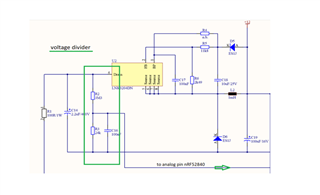
The voltage level of the input capacitor C14, 2.2µF / 400V to the Step-Down controller must be monitored. A voltage divider is used across the capacitor from R2, 3M3, and R3, 24k. The tapped voltage is measured at pin port P0.04 / AIN2 of the nRF52840. The expected voltage at the input of the controller is between 2.35V and 0V. The voltage at the capacitor must not fall below the value of 100V.

This is my requirement can anyone help how to configure SAADC with respect to my requirement.

Thanks in advance

Rohit R

  • Hi Karl,

    As you suggested I tried configuring my custom requirement in SDK example.

    My configurations,

        nrf_saadc_channel_config_t channel_config =
            NRF_DRV_SAADC_DEFAULT_CHANNEL_CONFIG_SE(NRF_SAADC_INPUT_AIN2);  //singale shot and channel config 
            
       channel_config.gain = NRF_SAADC_GAIN1_4;
       channel_config.reference = NRF_SAADC_REFERENCE_VDD4;
       channel_config.mode = NRF_SAADC_MODE_SINGLE_ENDED;
       channel_config.pin_n = NRF_SAADC_INPUT_DISABLED; 
       channel_config.pin_p = NRF_SAADC_INPUT_AIN2;
       channel_config.resistor_n = NRF_SAADC_RESISTOR_DISABLED;
       channel_config.resistor_p = NRF_SAADC_RESISTOR_DISABLED;

    After making changes in SDK example with the above configuration. When I followed the testing steps suggested for SDK example by Connecting pin to VDD and GND, I am still getting 10bit raw value. But I have configured for 12bit.

    Once I get exact raw values then I can apply voltage converter calculation as mentioned by you in the previous post.

    And one more thing I would like share is, my end device is Zigbee based Dimming control hardware. The selection of intensity levels is depended on the ADC values of the capacitor. More details you check mine below ticket where I have shared my schematic and details. This hardware is basically powered by 230V then using internal voltage converter we make 3V to power up nRF MCU.

    Please go through schematic also and let me know if I am making any mistakes in configuring SAADC.

    ticket link - https://devzone.nordicsemi.com/support/255201

    Thanks in advance

    Rohit R

  • Hello Rohit R,

    Rohit Rajapure said:
    My configurations,

    This is fine, with your code, you configure AIN2 channel to have 1/4 gain, VDD/4 reference and 10 us TAQ.
    Be advised that the NRF_DRV_SAADC_DEFAULT_CHANNEL_CONFIG_SE is a macro for setting up the default channel configurations. You may then change those that you do not want to be default. In your case, you are changing some things to the value that they already hold, which is why I am mentioning this.

    Rohit Rajapure said:
    After making changes in SDK example with the above configuration. When I followed the testing steps suggested for SDK example by Connecting pin to VDD and GND, I am still getting 10bit raw value. But I have configured for 12bit.

     The SAADC example is using 10 bit resolution as default. Could you show me where you have changed this to 12 bit? Also, this is not done as part of the channel configuration, but rather as part of the SAADC configuration.

    Rohit Rajapure said:
    Once I get exact raw values then I can apply voltage converter calculation as mentioned by you in the previous post.

    Yes, lets ensure that you are getting the correct raw SAADC output values first. This is a good approach.

    Rohit Rajapure said:
    Please go through schematic also and let me know if I am making any mistakes in configuring SAADC.

    What specifically would you like me to take a look at in your schematics / in your other ticket?
    It seems to me that you are getting good help by my colleague Jørgen in the other ticket.

    As for the SAADC configuration, you still have not told me what your required resolution for the project is, and what your intended sampling frequency is.

    Best regards,
    Karl

  • Hi,

    Be advised that the NRF_DRV_SAADC_DEFAULT_CHANNEL_CONFIG_SE is a macro for setting up the default channel configurations. You may then change those that you do not want to be default. In your case, you are changing some things to the value that they already hold, which is why I am mentioning this.

    - I did configuration as below,

      nrf_saadc_channel_config_t channel_config;     
       channel_config.gain = NRF_SAADC_GAIN1_4;
       channel_config.reference = NRF_SAADC_REFERENCE_VDD4;
       channel_config.mode = NRF_SAADC_MODE_SINGLE_ENDED;
       channel_config.pin_n = NRF_SAADC_INPUT_DISABLED; 
       channel_config.pin_p = NRF_SAADC_INPUT_AIN2;
       channel_config.resistor_n = NRF_SAADC_RESISTOR_DISABLED;
       channel_config.resistor_p = NRF_SAADC_RESISTOR_DISABLED;
    

     The SAADC example is using 10 bit resolution as default. Could you show me where you have changed this to 12 bit? Also, this is not done as part of the channel configuration, but rather as part of the SAADC configuration.

    - I set resolution here and in sdk_config.h file to

        nrf_drv_saadc_config_t saadc_config;
        saadc_config.resolution = NRF_SAADC_RESOLUTION_12BIT;   //12 bit resolution

    // <0=> 8 bit 
    // <1=> 10 bit 
    // <2=> 12 bit 
    // <3=> 14 bit 
    
    #ifndef NRFX_SAADC_CONFIG_RESOLUTION
    #define NRFX_SAADC_CONFIG_RESOLUTION 2
    #endif
    

    What specifically would you like me to take a look at in your schematics / in your other ticket?
    It seems to me that you are getting good help by my colleague Jørgen in the other ticket.

    - In the previous post, you had asked for the powering procedure of the device. So I shared this ticket and asked to go through the schematic more clear picture about powering MCU and ADC input pin related details.

    As for the SAADC configuration, you still have not told me what your required resolution for the project is, and what your intended sampling frequency is.

    - What I was informed is by a customer about capacitor voltage should be as below,

    "a voltage of capacitor<100V  (This corresponds to a voltage of 0.72V on

      Analog input of the nRF528)"

    - So I need an 8bit resolution sufficient for me but I was trying with 12bit and sampling frequency 50Hz.

    - In both 8bit and 12bit resolution also I am getting 10bit values 1023 when connecting to VDD.

    Please correct If am doing wrong, As my capacitor pin is connected to AIN2/P0_4 so I have to short P0_4 to VDD/GND to check values correct?

    As mentioned above snippet, I set the resolution as 12bit in both files still I am getting 1023 raw values when I connect to VDD.

    Can you let me know your views on this?

    Thanks and Regards

    Rohit R

  • Hi Karl,

    It's my fault. I have resolved the resolution issue.

    I am getting 8bit raw values and able to print on putty.

    Now, my next step is to convert  into voltage range.

        err_code = nrf_drv_saadc_init(&saadc_config, saadc_callback);
        APP_ERROR_CHECK(err_code);

    - I have forgot to call saadc_config parameter in init function. I kept it NULL.

    it's my fault.

    Thanks and Regards

    Rohit R

  • Hello Rohit,

    Rohit Rajapure said:
    I have resolved the resolution issue.

    I am happy to hear that you were able to resolve your issue!

    Rohit Rajapure said:
    I am getting 8bit raw values and able to print on putty.

    As I had understood it, you needed 12 bit resolution. Are you able to reconfigure to 12 bit resolution now?

    Rohit Rajapure said:
    - I have forgot to call saadc_config parameter in init function. I kept it NULL.

    I see. To avoid this in the future, I would advise that you remove obsolete code from your project instead of commenting it out - this increases readability tenfold.
    If you are worried that you will need the commented out code later, place it in a temporary work file.

    Please do not hesitate to open a new ticket if you should encounter any other issues or questions in the future.

    Good luck with your development!

    Best regards,
    Karl

Related