This post is older than 2 years and might not be relevant anymore
More Info: Consider searching for newer posts

No readings from LSM9DS1 using TWI example

Hi all,

Currently employing my custom board definition for Arduino Nano 33 BLE for use with the nRF5 SDK. So far I have gotten an array of examples working including the ANT+ Bike Power example. I am now porting LSM9DS1 drivers to use the Nano 33's built-in accelerometer.

I am using this repository as a guide: https://github.com/drvrh/nRF52-DK-and-LSM9DS1, but am using previous commits from 2018. I have attached the headers below. I have also attached my main file.

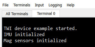
I added a few print functions to trace down the bug. Main function seems to pass through the error checks, twi initialization, and IMU/magnetic sensor initialization functions without issue as per my output in RTT Viewer (see below).

The code seems to get stuck here, where it gets the device ID's. It returns 0x0 for both the IMU and magnetic sensor so I am thinking that maybe the LSM9DS1 is not receiving power. The code seems to recognize that the LSM9DS1 exists because it does not return the "Cannot find the LSM9DS1." error message.

/* Check device ID */
    lsm9ds1_dev_id_get(&dev_ctx_mag, &dev_ctx_imu, &whoamI);
    if (whoamI.imu != LSM9DS1_IMU_ID || whoamI.mag != LSM9DS1_MAG_ID){
      while(1){
        /* manage here device not found */
        NRF_LOG_INFO("\r\nCannot find the LSM9DS1.********\r\n");
        //NRF_LOG_FLUSH();
        printf("\r\nCannot find the LSM9DS1.********\r\n");
      }
    }
   printf("Who am I register [IMU]: 0x%x [MAG]: 0x%x \r\n", whoamI.imu, whoamI.mag); 

As the Nano 33 becomes increasingly popular, it would be helpful to get this issue resolved for the developer seeking to employ the more powerful nRF5 SDK on his/her Nano 33 prototypes. I am asking for guidance on this issue to help me sniff out where the issue possibly could be.

Note: Also working with the TWI scanner example. Same issue here... getting stuck in the device id portion of the code.

Output:

Attachments:

/cfs-file/__key/support-attachments/beef5d1b77644c448dabff31668f3a47-674ed7a0103a46929140932128e07649/lsm9ds1_5F00_reg.c

/cfs-file/__key/support-attachments/beef5d1b77644c448dabff31668f3a47-674ed7a0103a46929140932128e07649/lsm9ds1_5F00_reg.h

Parents
  • Hi,

    Note: Also working with the TWI scanner example. Same issue here... getting stuck in the device id portion of the code.

    It is not clear to me whether you are able to communicate with the slave device at all. Are you? What happens if you use an unmodified TWI scanner example? Is the slave found? If not, we need to look at that first, so make sure the basics are in place.

  • Here is the schematic I'm dealing with. We have a VDD, SDA1, SCL1, and of course ground connections being made. Arduino did a silly thing not to include the interrupt pin but that's a different issue.

    I'm testing with only the unmodified scanner example now. Unable to communicate with the slave whatsoever. Debugging currently but still unsure of the issue. I wonder if it has to do with a pullup.

  • Pull-ups are 4k7, which is fine for 100KHz but with multiple devices the nRF52 will struggle to get good low-level drive on the settings you are using. Try switching to H0D1 (High Drive '0', Disconnect Drive '1') thus:

    void twi_init (void)
    {
        ret_code_t err_code;
        const nrf_drv_twi_config_t twi_config = {
           .scl                = ARDUINO_SCL1_PIN,
           .sda                = ARDUINO_SDA1_PIN,
           .frequency          = NRF_DRV_TWI_FREQ_100K,
           .interrupt_priority = APP_IRQ_PRIORITY_HIGH,
           .clear_bus_init     = false
        };
        err_code = nrf_drv_twi_init(&m_twi, &twi_config, NULL, NULL);
        APP_ERROR_CHECK(err_code);
        nrf_drv_twi_enable(&m_twi);
        // To secure correct signal levels on the pins used by the TWI master when the system is in OFF mode, and
        // when the TWI master is disabled, SDA and SCL pins must be configured in the GPIO peripheral as follows:
        // SCL As specified in PSEL.SCL: Input H0D1
        // SDA As specified in PSEL.SDA: Input H0D1
        nrf_gpio_cfg(ARDUINO_SDA1_PIN, NRF_GPIO_PIN_DIR_INPUT, NRF_GPIO_PIN_INPUT_CONNECT, NRF_GPIO_PIN_PULLUP, NRF_GPIO_PIN_H0D1, NRF_GPIO_PIN_NOSENSE);
        nrf_gpio_cfg(ARDUINO_SCL1_PIN, NRF_GPIO_PIN_DIR_INPUT, NRF_GPIO_PIN_INPUT_CONNECT, NRF_GPIO_PIN_PULLUP, NRF_GPIO_PIN_H0D1, NRF_GPIO_PIN_NOSENSE);
    }
    

Reply
  • Pull-ups are 4k7, which is fine for 100KHz but with multiple devices the nRF52 will struggle to get good low-level drive on the settings you are using. Try switching to H0D1 (High Drive '0', Disconnect Drive '1') thus:

    void twi_init (void)
    {
        ret_code_t err_code;
        const nrf_drv_twi_config_t twi_config = {
           .scl                = ARDUINO_SCL1_PIN,
           .sda                = ARDUINO_SDA1_PIN,
           .frequency          = NRF_DRV_TWI_FREQ_100K,
           .interrupt_priority = APP_IRQ_PRIORITY_HIGH,
           .clear_bus_init     = false
        };
        err_code = nrf_drv_twi_init(&m_twi, &twi_config, NULL, NULL);
        APP_ERROR_CHECK(err_code);
        nrf_drv_twi_enable(&m_twi);
        // To secure correct signal levels on the pins used by the TWI master when the system is in OFF mode, and
        // when the TWI master is disabled, SDA and SCL pins must be configured in the GPIO peripheral as follows:
        // SCL As specified in PSEL.SCL: Input H0D1
        // SDA As specified in PSEL.SDA: Input H0D1
        nrf_gpio_cfg(ARDUINO_SDA1_PIN, NRF_GPIO_PIN_DIR_INPUT, NRF_GPIO_PIN_INPUT_CONNECT, NRF_GPIO_PIN_PULLUP, NRF_GPIO_PIN_H0D1, NRF_GPIO_PIN_NOSENSE);
        nrf_gpio_cfg(ARDUINO_SCL1_PIN, NRF_GPIO_PIN_DIR_INPUT, NRF_GPIO_PIN_INPUT_CONNECT, NRF_GPIO_PIN_PULLUP, NRF_GPIO_PIN_H0D1, NRF_GPIO_PIN_NOSENSE);
    }
    

Children
Related