
I'm using Ubuntu 20.04, SES 4.52c, SDK 16 nRF52840 DK board.
I'm going to need to use the PWM driver to supply clock pulses to an I2S microphone and the I2S peripheral running in slave mode. So I decided to practice a little with the PWM driver. I started out with the PWM Library but it quickly became apparent that the PWM Library wasn't going to work for my needs.
I'm using the following code to mess around with square wave production. The square wave should have a 50% duty cycle by definition. All I want is two square waves with two different frequencies.
#define PWM_I2S_SCK_PIN     NRF_GPIO_PIN_MAP(1, 01)           // I2S SCK pin for PWM-synthesized I2S clocks
#define PWM_I2S_WS_PIN      NRF_GPIO_PIN_MAP(1, 02)           // I2S LRCK pin for PWM-synthesized I2S clocks
#define I2S_MIC_POWER       NRF_GPIO_PIN_MAP(1, 03)

#define TOP_VAL           4
static nrf_pwm_values_common_t seq_values[] = {(TOP_VAL / 2)};
nrf_pwm_sequence_t const seq =
{
    .values.p_common     = seq_values,
    .length              = NRF_PWM_VALUES_LENGTH(seq_values),
    .repeats             = 0,
    .end_delay           = 0
};

nrfx_pwm_config_t const config_sck =
{
    .output_pins =
    {
        PWM_I2S_SCK_PIN,       // channel 0
        NRFX_PWM_PIN_NOT_USED, // channel 1
        NRFX_PWM_PIN_NOT_USED, // channel 2
        NRFX_PWM_PIN_NOT_USED  // channel 3
    },
    .irq_priority = APP_IRQ_PRIORITY_LOWEST,
    .base_clock   = NRF_PWM_CLK_8MHz,
    .count_mode   = NRF_PWM_MODE_UP,
    .top_value    = TOP_VAL,
    .load_mode    = NRF_PWM_LOAD_COMMON,
    .step_mode    = NRF_PWM_STEP_AUTO
};
static nrfx_pwm_t m_pwm2_sck = NRFX_PWM_INSTANCE(2);


nrfx_pwm_config_t const config_lrck =
{
    .output_pins =
    {
        PWM_I2S_WS_PIN,        // channel 0
        NRFX_PWM_PIN_NOT_USED, // channel 1
        NRFX_PWM_PIN_NOT_USED, // channel 2
        NRFX_PWM_PIN_NOT_USED  // channel 3
    },
    .irq_priority = APP_IRQ_PRIORITY_LOWEST,
    .base_clock   = NRF_PWM_CLK_8MHz,
    .count_mode   = NRF_PWM_MODE_UP,
    .top_value    = TOP_VAL,
    .load_mode    = NRF_PWM_LOAD_COMMON,
    .step_mode    = NRF_PWM_STEP_AUTO
};
static nrfx_pwm_t m_pwm3_lrck = NRFX_PWM_INSTANCE(3);


int main(void)
{
    bool              result = true;
    char              c = 0;
    uint32_t          err_code = NRF_SUCCESS;

    // "To ensure correct behavior in the PWM module, the pins that are used must be configured in the GPIO peripheral
    // as Output and Output 0 before the PWM module is enabled:"
    nrf_gpio_cfg_output(PWM_I2S_SCK_PIN);
    nrf_gpio_pin_clear(PWM_I2S_SCK_PIN);
    nrf_gpio_cfg_output(PWM_I2S_WS_PIN);
    nrf_gpio_pin_clear(PWM_I2S_WS_PIN);

    for (;;)
    {

        c = SEGGER_RTT_WaitKey(); // will block until data is available
        if (c == 's')
        {
            // "If NULL is passed, event notifications are not done and PWM interrupts are disabled."
            err_code = nrfx_pwm_init(&m_pwm2_sck, &config_sck, NULL);
            APP_ERROR_CHECK(err_code);
            err_code = nrfx_pwm_simple_playback(&m_pwm2_sck, &seq, 1, NRFX_PWM_FLAG_LOOP);
        }
        else if (c == 'd')
        {
            err_code = nrfx_pwm_init(&m_pwm3_lrck, &config_lrck, NULL);
            APP_ERROR_CHECK(err_code);
            err_code = nrfx_pwm_simple_playback(&m_pwm3_lrck, &seq, 1, NRFX_PWM_FLAG_LOOP);
        }
        else if (c == 'c')
        {
            // "If NULL is passed, event notifications are not done and PWM interrupts are disabled."
            err_code = nrfx_pwm_init(&m_pwm2_sck, &config_sck, NULL);
            APP_ERROR_CHECK(err_code);
            err_code = nrfx_pwm_simple_playback(&m_pwm2_sck, &seq, 1, NRFX_PWM_FLAG_LOOP);

            err_code = nrfx_pwm_init(&m_pwm3_lrck, &config_lrck, NULL);
            APP_ERROR_CHECK(err_code);
            err_code = nrfx_pwm_simple_playback(&m_pwm3_lrck, &seq, 1, NRFX_PWM_FLAG_LOOP);
        }
        else if (c == 'v')
        {
            result = nrfx_pwm_is_stopped(&m_pwm2_sck);
            if (!result)
            {
                // If 2nd parameter is true, the function will not return until the playback is stopped.
                result = nrfx_pwm_stop(&m_pwm2_sck, 1);
            }
            nrfx_pwm_uninit (&m_pwm2_sck);

            result = nrfx_pwm_is_stopped(&m_pwm3_lrck);
            if (!result)
            {
                result = nrfx_pwm_stop(&m_pwm3_lrck, 1);
            }
            nrfx_pwm_uninit (&m_pwm3_lrck);
        }

    }
}
Question 1: How do you use .top_value and nrf_pwm_values_common_t seq_values[] to produce a 50% duty cycle?
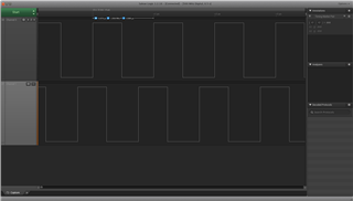
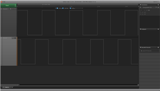
I've figured out that for a 50% duty cycle, sequence has to be 1/2 of top value but when you look at these two screen shots you can see that the peak and the trough have different widths. Is that to be expected and is it unavoidable?
Question 2: Is there anyway of starting two separate nrfx_pwm_config_t instances simultaneously?
You can see in the screen shots that the 2nd channel is slightly ahead of the 1st channel. This delay is no doubt caused by the sequential calls to nrfx_pwm_simple_playback to start each of the channels. I guess the only way is to use two of the four channels in one instances of a nrfx_pwm_config_t. If I wanted my 2nd channel to have a duty cycle that was 32x's larger than my first channel, how would I put the sequence array together?
Question 3: Is there any reason GPIO pins 0.00 through 0.10 wouldn't be available for use by the PWM Driver?
I originally tried to use those pins on the DK board but never got a signal out. Pins 1.01 through 1.15 work just fine.
Thank you for any advice and help.

