
Hello,
I am testing direction finding over nRF5340 PDK.
I didn't have antenna array yet, but I think that's equivalent to signal received at 90 degree.
I have two questions:
=========================
1. number of I/Q samples
I have configured
- sampling interval at REF to 125ns
- sampling interval at switch period to 125ns
- CTE length to 24 us
- Switching interval to 2 us
I consider the number of samples to transfer is calculated as: 8/0.125 + (24-12)/2 )/0.125 = 64 + 48 = 112 samples.
However when I read the AMOUNT register, it gives 160: which I assume it calculated as 8/0.125 + (24-12)/0.125 = 64 + 96 = 160 samples.
This means the sampling is not only happening during sampling slot, but both the switch slot and sampling slot. Is this what chip is doing?
=========================
2. sampling offset
I have plotted the result as shown in figure below:
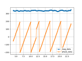
The x axis is time, the data starts at 4us indicating the start of reference period. I mapped the data from 4us to 24 us with 0.125 spacing. This maybe is wrong but I don't know for the moment what is the right timestamp for the I/Q sample data.
You can see there is a disconnection from 12us when the reference period ends. Is this the sample offset indicated in the production specification? I configured to 3 (3@16M = 0.1875us, which is probably not enough. I have shift the right part by 1us on the timing, which makes the wave looks continuously.
Could someone help me to understand when those samples are taken exactly ? Thanks a lot!
Tengfei
