This post is older than 2 years and might not be relevant anymore
More Info: Consider searching for newer posts

How fast can the counter count?

I'm using an nRF52840-Preview-DK board in a POC (Proof Of Concept) to convert an I2S-TDM bus to SPI.

So it takes the I2S FS (frame sync) and CLK (clock) signals as inputs and generates the SPI CSN (chip select) signal 

Then the I2S clock and data signals pass through unmodified to the SPI bus clock and data signals.

TIMER0 is in counter mode.

I have PPI setup so that:

  • when FS goes high, CSN goes low and TIMER0 is cleared
  • when CLK goes high, TIMER0 counts (TASK_COUNT)
  • when TIMER0 COMPARE0 matches, CSN goes high

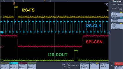
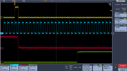
The problem is that when CSN goes high, about twice as many clocks have happened as expected, and its not always consistent.  I'm testing with a CC0 of 10 and I'm seeing 17-20 clocks happening between CSN low and CSN high

So I suspect that the GPIOTE edge detection / TASK_COUNT is not keeping up.

CLK is running at 3.072MHz, so low-to-high edges happen every 326ns

I haven't found any specs on the max rate that the counter can count at.

What is that spec?

Parents
  • The preview DK likely has a few erratas, you really need to get a newer DK. 

    Do you have a scope of the SPI and I2S communication? 

    The GPIOTE tasks should only be delayed by one 16MHz clock cycle, 62.5ns. There is however some delay in the GPIO peripheral, but that should be much lower than one 16MHz clock cycle. 


    So it takes the I2S FS (frame sync) and CLK (clock) signals as inputs and generates the SPI CSN (chip select) signal 

    Then the I2S clock and data signals pass through unmodified to the SPI bus clock and data signals.

     Have I understood you correctly that the nRF52 operates as an I2S slave and a SPI master? 

    Then the I2S clock and data signals pass through unmodified to the SPI bus clock and data signals.

     Can you elaborate? 
    Do you mean that you share the DMA buffer between the I2S and SPI peripheral? 

  • I looked through the errata on the processor in the PDK board and didn't see a problem, but I'm getting a DK board just to be sure.

    Sorry, I probably gave too much detail and it's confusing you.

    I'm not using the I2S or SPI peripherals on the nRF52840 at all.  

    The I2S is coming from an Audio ADC chip and has 8 channels of audio, so it uses TDM.

    The SPI bus is going to an nRF5340 (we had to use SPI because the I2S peripheral on the nRF5340 only supports stereo audio - not 8 channels)

    I'm only using GPIOTE, PPI and TIMER0 on the nRF52840.

    The nRF53840 is between the Audio ADC and the nRF5340.

    You can ignore the fact that its implementing an I2S to SPI converter.

    Here's the source code

    #include <stdbool.h>
    #include <stdint.h>
    #include "nrf_delay.h"
    #include "boards.h"
    
    #include "app_error.h"
    
    #include "nrf_drv_ppi.h"
    #include "nrf_drv_timer.h"
    
    #include "nrf_log.h"
    #include "nrf_log_ctrl.h"
    #include "nrf_log_default_backends.h"
    
    #include "nrf.h"
    #include "nrf_gpiote.h"
    #include "nrf_gpio.h"
    #include "nrf_drv_gpiote.h"


    // I2S bus
    #define I2S_FS_PIN    NRF_GPIO_PIN_MAP(0,6)  //I2S FrameSync pin
    #define I2S_CLK_PIN   NRF_GPIO_PIN_MAP(0,7)  //I2S clock pin
    
    // SPI bus
    #define SPI_CSN_PIN   NRF_GPIO_PIN_MAP(0,8)  //SPI chip select pin
    #define SPI_SCK_PIN   NRF_GPIO_PIN_MAP(0,5)  //SPI clock pin
    
    // state machine
    #define CLOCKS_PER_MESSAGE  10 // max number of bits in a single I2S message.  Should be 128 for 8 channels of 16-bit audio (8*16 = 128)
    
    static const nrf_drv_timer_t m_timer0 = NRF_DRV_TIMER_INSTANCE(0);
    
    static nrf_ppi_channel_t m_ppi_channel_fs_start;
    static nrf_ppi_channel_t m_ppi_channel_counter_end;
    static nrf_ppi_channel_t m_ppi_channel_tick;
    
    static uint32_t clocks_per_fs = 0;
    static uint32_t max_clocks_per_fs = 0;
    
    
    static void gpio_init(void)
    {
      nrf_gpio_pin_set(SPI_CSN_PIN);
      nrf_gpio_cfg_output(SPI_CSN_PIN);
    
      nrf_gpio_pin_clear(SPI_SCK_PIN);
      nrf_gpio_cfg_output(SPI_SCK_PIN);
    
      nrf_gpio_cfg_input(I2S_FS_PIN, NRF_GPIO_PIN_NOPULL);
      nrf_gpio_cfg_input(I2S_CLK_PIN, NRF_GPIO_PIN_NOPULL);
    }
    
    // I2S_FS 
    void gpiote_fs_handler(nrfx_gpiote_pin_t pin, nrf_gpiote_polarity_t action)
    {
    #if 0
        if(!nrf_drv_timer_is_enabled(&m_timer0))
        {
          nrf_drv_timer_enable(&m_timer0);
        }
    #endif
    
    #if 0
        if(clocks_per_fs > max_clocks_per_fs) max_clocks_per_fs = clocks_per_fs;
        clocks_per_fs = 0;
    #endif
    }
    
    // I2S_CLK
    void gpiote_clk_handler(nrfx_gpiote_pin_t pin, nrf_gpiote_polarity_t action)
    {
    #if 0
      clocks_per_fs++;
    #endif
    }
    
    static void gpiote_init(void)
    {
        ret_code_t err_code;
    
        err_code = nrf_drv_gpiote_init();
        APP_ERROR_CHECK(err_code);
    }
    
    
    static void ppi_init(void)
    {
        uint32_t err_code = NRF_SUCCESS;
    
        err_code = nrf_drv_ppi_init();
        APP_ERROR_CHECK(err_code);
    
        // Configure 1st available PPI channel to clear the TIMER0 counter on I2S_FS pin going high,
        err_code = nrf_drv_ppi_channel_alloc(&m_ppi_channel_fs_start);
        APP_ERROR_CHECK(err_code);
    
        nrf_drv_gpiote_in_config_t fs_config = GPIOTE_CONFIG_IN_SENSE_LOTOHI(true);
        err_code = nrf_drv_gpiote_in_init(I2S_FS_PIN, &fs_config, gpiote_fs_handler);
        APP_ERROR_CHECK(err_code);
        uint32_t gpiote_fs_event_addr = nrf_drv_gpiote_in_event_addr_get(I2S_FS_PIN);
    
        err_code = nrf_drv_ppi_channel_assign(m_ppi_channel_fs_start,
                                              gpiote_fs_event_addr,
                                              nrf_drv_timer_task_address_get(&m_timer0,
                                              NRF_TIMER_TASK_CLEAR));
        APP_ERROR_CHECK(err_code);
    
        // Configure the 1st PPI channel to also clear the SPI_CSN pin
        nrf_drv_gpiote_out_config_t csn_lo_config = GPIOTE_CONFIG_OUT_TASK_LOW;
        csn_lo_config.init_state = NRF_GPIOTE_INITIAL_VALUE_HIGH;
        err_code = nrf_drv_gpiote_out_init(SPI_CSN_PIN, &csn_lo_config);
        APP_ERROR_CHECK(err_code);
        uint32_t gpiote_csn_lo_task_addr = nrfx_gpiote_clr_task_addr_get(SPI_CSN_PIN);
    
        err_code = nrf_drv_ppi_channel_fork_assign(m_ppi_channel_fs_start, gpiote_csn_lo_task_addr);
        APP_ERROR_CHECK(err_code);


        // Configure 2nd available PPI channel to set SPI_CSN high at TIMER0 COMPARE[0] match,
        err_code = nrf_drv_ppi_channel_alloc(&m_ppi_channel_counter_end);
        APP_ERROR_CHECK(err_code);
    
        uint32_t gpiote_csn_hi_task_addr = nrfx_gpiote_set_task_addr_get(SPI_CSN_PIN);
    
        err_code = nrf_drv_ppi_channel_assign(m_ppi_channel_counter_end,
                                              nrf_drv_timer_event_address_get(&m_timer0,
                                              NRF_TIMER_EVENT_COMPARE0),
                                              gpiote_csn_hi_task_addr);
        APP_ERROR_CHECK(err_code);
    
    
        // Configure 3rd available PPI channel to increment TIMER0 each time I2S_CLK toggles low-to-high
        err_code = nrf_drv_ppi_channel_alloc(&m_ppi_channel_tick);
        APP_ERROR_CHECK(err_code);
    
        nrf_drv_gpiote_in_config_t clk_config = GPIOTE_CONFIG_IN_SENSE_LOTOHI(true);
        err_code = nrf_drv_gpiote_in_init(I2S_CLK_PIN, &clk_config, gpiote_clk_handler);
        APP_ERROR_CHECK(err_code);
        uint32_t gpiote_clk_event_addr = nrf_drv_gpiote_in_event_addr_get(I2S_CLK_PIN);
    
        err_code = nrf_drv_ppi_channel_assign(m_ppi_channel_tick,
                                              gpiote_clk_event_addr,
                                              nrf_drv_timer_task_address_get(&m_timer0,
                                              NRF_TIMER_TASK_COUNT));
        APP_ERROR_CHECK(err_code);
    
    
        // Enable configured PPI channels
        err_code = nrf_drv_ppi_channel_enable(m_ppi_channel_fs_start);
        APP_ERROR_CHECK(err_code);
        err_code = nrf_drv_ppi_channel_enable(m_ppi_channel_counter_end);
        APP_ERROR_CHECK(err_code);
        err_code = nrf_drv_ppi_channel_enable(m_ppi_channel_tick);
        APP_ERROR_CHECK(err_code);
    
        // Enable applicable events and tasks
        nrf_drv_gpiote_in_event_enable(I2S_FS_PIN, true);
        nrf_drv_gpiote_out_task_enable(SPI_CSN_PIN);
        nrf_drv_gpiote_in_event_enable(I2S_CLK_PIN, true);
    }
    
    static void timer0_event_handler(nrf_timer_event_t event_type, void * p_context)
    {
    }
    
    static void timer0_init(void)
    {
        // Check TIMER0 configuration for details.
        nrf_drv_timer_config_t timer_cfg = NRF_DRV_TIMER_DEFAULT_CONFIG;
        timer_cfg.mode = NRF_TIMER_MODE_COUNTER;
        timer_cfg.bit_width = NRF_TIMER_BIT_WIDTH_16;
        ret_code_t err_code = nrf_drv_timer_init(&m_timer0, &timer_cfg, timer0_event_handler);
        APP_ERROR_CHECK(err_code);
    
        nrf_drv_timer_compare(&m_timer0,
                              NRF_TIMER_CC_CHANNEL0,
                              CLOCKS_PER_MESSAGE,
                              true);
    
        nrf_drv_timer_enable(&m_timer0);
    }
    
    static void clock_init(void)
    {
        // Start 32 MHz crystal oscillator .
        NRF_CLOCK->EVENTS_HFCLKSTARTED = 0;
        NRF_CLOCK->TASKS_HFCLKSTART    = 1;
    
        // Wait for the external oscillator to start up.
        while (NRF_CLOCK->EVENTS_HFCLKSTARTED == 0) {
        }
    }
    
    int main(void)
    {
      // Configure board 
      clock_init();
      gpio_init();
      gpiote_init();
      ppi_init();
      timer0_init();
    
      uint32_t i = 0;
      // State Machine
      while (true)
      {
        i++;
      }
    }
    
    /**
     *@}
     **/
    

    Here's an oscilloscope trace

    Once SPI-CSN goes low, I want it to go high again after 10 clocks of I2S-CLK (10 is just a number I chose for test - The actual implementation will use 128 clocks)

    It doesn't actually go high until after 18-19 clocks, depending on whether you count the one that occurs at the same time that SPI-CSN is going low.  And its not always the same number - sometimes is 16 and other times 20.

  • Thank you for the detailed explanation, I think I understand what the issue is now. 

    There might be a race condition somewhere. 

    I suggest you map the SPI-CSN transition from low to high to a separate GPIO pin and see if it will trigger the transition correctly, I'm curious to see what happens when there's only one GPIOTE channel controlling the pin during this transition. 


  • Using a separate pin for low-to-high transition did not fix it.

    The green trace is this new pin (SPI_CSN2_PIN).  There are still 17 clocks instead of 10 between CSN going low and CSN2 going high

    Here's the new source code

    #include <stdbool.h>
    #include <stdint.h>
    #include "nrf_delay.h"
    #include "boards.h"
    
    #include "app_error.h"
    
    #include "nrf_drv_ppi.h"
    #include "nrf_drv_timer.h"
    
    #include "nrf_log.h"
    #include "nrf_log_ctrl.h"
    #include "nrf_log_default_backends.h"
    
    #include "nrf.h"
    #include "nrf_gpiote.h"
    #include "nrf_gpio.h"
    #include "nrf_drv_gpiote.h"


    // I2S bus
    #define I2S_FS_PIN    NRF_GPIO_PIN_MAP(0,6)  //I2S FrameSync pin
    #define I2S_CLK_PIN   NRF_GPIO_PIN_MAP(0,7)  //I2S clock pin
    
    // SPI bus
    #define SPI_CSN_PIN   NRF_GPIO_PIN_MAP(0,8)  //SPI chip select pin
    #define SPI_CSN2_PIN   NRF_GPIO_PIN_MAP(0,5)  //SPI chip select pin 2 for debug
    
    // state machine
    #define CLOCKS_PER_MESSAGE  10 // max number of bits in a single I2S message.  Should be 128 for 8 channels of 16-bit audio (8*16 = 128)
    
    static const nrf_drv_timer_t m_timer0 = NRF_DRV_TIMER_INSTANCE(0);
    
    static nrf_ppi_channel_t m_ppi_channel_fs_start;
    static nrf_ppi_channel_t m_ppi_channel_counter_end;
    static nrf_ppi_channel_t m_ppi_channel_tick;
    
    static uint32_t clocks_per_fs = 0;
    static uint32_t max_clocks_per_fs = 0;
    
    
    static void gpio_init(void)
    {
      nrf_gpio_pin_set(SPI_CSN_PIN);
      nrf_gpio_cfg_output(SPI_CSN_PIN);
    
      nrf_gpio_pin_clear(SPI_CSN2_PIN);
      nrf_gpio_cfg_output(SPI_CSN2_PIN);
    
      nrf_gpio_cfg_input(I2S_FS_PIN, NRF_GPIO_PIN_NOPULL);
      nrf_gpio_cfg_input(I2S_CLK_PIN, NRF_GPIO_PIN_NOPULL);
    }
    
    // I2S_FS 
    void gpiote_fs_handler(nrfx_gpiote_pin_t pin, nrf_gpiote_polarity_t action)
    {
    #if 0
        if(!nrf_drv_timer_is_enabled(&m_timer0))
        {
          nrf_drv_timer_enable(&m_timer0);
        }
    #endif
    
    #if 0
        if(clocks_per_fs > max_clocks_per_fs) max_clocks_per_fs = clocks_per_fs;
        clocks_per_fs = 0;
    #endif
    }
    
    // I2S_CLK
    void gpiote_clk_handler(nrfx_gpiote_pin_t pin, nrf_gpiote_polarity_t action)
    {
    #if 0
      clocks_per_fs++;
    #endif
    }
    
    static void gpiote_init(void)
    {
        ret_code_t err_code;
    
        err_code = nrf_drv_gpiote_init();
        APP_ERROR_CHECK(err_code);
    }
    
    
    static void ppi_init(void)
    {
        uint32_t err_code = NRF_SUCCESS;
    
        err_code = nrf_drv_ppi_init();
        APP_ERROR_CHECK(err_code);
    
        // Configure 1st available PPI channel to clear the TIMER0 counter on I2S_FS pin going high,
        err_code = nrf_drv_ppi_channel_alloc(&m_ppi_channel_fs_start);
        APP_ERROR_CHECK(err_code);
    
        nrf_drv_gpiote_in_config_t fs_config = GPIOTE_CONFIG_IN_SENSE_LOTOHI(true);
        err_code = nrf_drv_gpiote_in_init(I2S_FS_PIN, &fs_config, gpiote_fs_handler);
        APP_ERROR_CHECK(err_code);
        uint32_t gpiote_fs_event_addr = nrf_drv_gpiote_in_event_addr_get(I2S_FS_PIN);
    
        err_code = nrf_drv_ppi_channel_assign(m_ppi_channel_fs_start,
                                              gpiote_fs_event_addr,
                                              nrf_drv_timer_task_address_get(&m_timer0,
                                              NRF_TIMER_TASK_CLEAR));
        APP_ERROR_CHECK(err_code);
    
        // Configure the 1st PPI channel to also clear the SPI_CSN pin
        nrf_drv_gpiote_out_config_t csn_lo_config = GPIOTE_CONFIG_OUT_TASK_LOW;
        csn_lo_config.init_state = NRF_GPIOTE_INITIAL_VALUE_HIGH;
        err_code = nrf_drv_gpiote_out_init(SPI_CSN_PIN, &csn_lo_config);
        APP_ERROR_CHECK(err_code);
        uint32_t gpiote_csn_lo_task_addr = nrfx_gpiote_clr_task_addr_get(SPI_CSN_PIN);
    
        err_code = nrf_drv_ppi_channel_fork_assign(m_ppi_channel_fs_start, gpiote_csn_lo_task_addr);
        APP_ERROR_CHECK(err_code);


        // Configure 2nd available PPI channel to set SPI_CSN high at TIMER0 COMPARE[0] match,
        err_code = nrf_drv_ppi_channel_alloc(&m_ppi_channel_counter_end);
        APP_ERROR_CHECK(err_code);
    
        nrf_drv_gpiote_out_config_t csn_hi_config = GPIOTE_CONFIG_OUT_TASK_HIGH;
        csn_hi_config.init_state = NRF_GPIOTE_INITIAL_VALUE_LOW;
        err_code = nrf_drv_gpiote_out_init(SPI_CSN2_PIN, &csn_hi_config);
        APP_ERROR_CHECK(err_code);
        uint32_t gpiote_csn_hi_task_addr = nrfx_gpiote_set_task_addr_get(SPI_CSN2_PIN);
    
        err_code = nrf_drv_ppi_channel_assign(m_ppi_channel_counter_end,
                                              nrf_drv_timer_event_address_get(&m_timer0,
                                              NRF_TIMER_EVENT_COMPARE0),
                                              gpiote_csn_hi_task_addr);
        APP_ERROR_CHECK(err_code);
    
    
        // Configure 3rd available PPI channel to increment TIMER0 each time I2S_CLK toggles low-to-high
        err_code = nrf_drv_ppi_channel_alloc(&m_ppi_channel_tick);
        APP_ERROR_CHECK(err_code);
    
        nrf_drv_gpiote_in_config_t clk_config = GPIOTE_CONFIG_IN_SENSE_LOTOHI(true);
        err_code = nrf_drv_gpiote_in_init(I2S_CLK_PIN, &clk_config, gpiote_clk_handler);
        APP_ERROR_CHECK(err_code);
        uint32_t gpiote_clk_event_addr = nrf_drv_gpiote_in_event_addr_get(I2S_CLK_PIN);
    
        err_code = nrf_drv_ppi_channel_assign(m_ppi_channel_tick,
                                              gpiote_clk_event_addr,
                                              nrf_drv_timer_task_address_get(&m_timer0,
                                              NRF_TIMER_TASK_COUNT));
        APP_ERROR_CHECK(err_code);
    
    
        // Enable configured PPI channels
        err_code = nrf_drv_ppi_channel_enable(m_ppi_channel_fs_start);
        APP_ERROR_CHECK(err_code);
        err_code = nrf_drv_ppi_channel_enable(m_ppi_channel_counter_end);
        APP_ERROR_CHECK(err_code);
        err_code = nrf_drv_ppi_channel_enable(m_ppi_channel_tick);
        APP_ERROR_CHECK(err_code);
    
        // Enable applicable events and tasks
        nrf_drv_gpiote_in_event_enable(I2S_FS_PIN, true);
        nrf_drv_gpiote_out_task_enable(SPI_CSN_PIN);
        nrf_drv_gpiote_out_task_enable(SPI_CSN2_PIN);
        nrf_drv_gpiote_in_event_enable(I2S_CLK_PIN, true);
    }
    
    static void timer0_event_handler(nrf_timer_event_t event_type, void * p_context)
    {
    }
    
    static void timer0_init(void)
    {
        // Check TIMER0 configuration for details.
        nrf_drv_timer_config_t timer_cfg = NRF_DRV_TIMER_DEFAULT_CONFIG;
        timer_cfg.mode = NRF_TIMER_MODE_COUNTER;
        timer_cfg.bit_width = NRF_TIMER_BIT_WIDTH_16;
        ret_code_t err_code = nrf_drv_timer_init(&m_timer0, &timer_cfg, timer0_event_handler);
        APP_ERROR_CHECK(err_code);
    
        nrf_drv_timer_compare(&m_timer0,
                              NRF_TIMER_CC_CHANNEL0,
                              CLOCKS_PER_MESSAGE,
                              true);
    
        nrf_drv_timer_enable(&m_timer0);
    }
    
    static void clock_init(void)
    {
        // Start 32 MHz crystal oscillator .
        NRF_CLOCK->EVENTS_HFCLKSTARTED = 0;
        NRF_CLOCK->TASKS_HFCLKSTART    = 1;
    
        // Wait for the external oscillator to start up.
        while (NRF_CLOCK->EVENTS_HFCLKSTARTED == 0) {
        }
    }
    
    int main(void)
    {
      // Configure board 
      clock_init();
      gpio_init();
      gpiote_init();
      ppi_init();
      timer0_init();
    
      uint32_t i = 0;
      // State Machine
      while (true)
      {
        i++;
      }
    }
    
    /**
     *@}
     **/
    

    What do you think the race condition may be?

  • By the way, I tested at half speed (I2S-CLK set to 1.536MHz instead of 3.072MHz) and that seemed to work.  The CSN pin goes high after 10 clock cycles.

    Isn't this much slower than expected?  I would think from your initial response that the GPIOTE/PPI circuits should be able to handle signals up to 8MHz or so.

  • Hi,

    it seems I2S-CLK is really too fast for GPIOTE. In this thread, Martin suggests no more than 2.67MHz for 50%-duty signal.

  • Did you try the workaround for errata 155? IN event may occur more than once on input edge that was nRF52832, same errata on nRF52840 here

Reply Children
Related