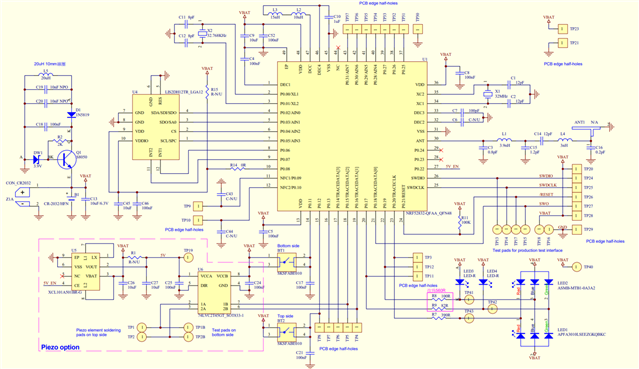
I got a nrf52832 custom board to communicate with LIS2DH12 accelerometer by I2C(TWI).
I edited part of the code from "twi_sensor" project in NRF5_SDK version 17.0.
I tried to read the "x_out_low " byte from LIS2DH12, but always get zero.
Here's my schematic diagram:
Here's my code:
/**
* Copyright (c) 2015 - 2020, Nordic Semiconductor ASA
*
* All rights reserved.
*
* Redistribution and use in source and binary forms, with or without modification,
* are permitted provided that the following conditions are met:
*
* 1. Redistributions of source code must retain the above copyright notice, this
* list of conditions and the following disclaimer.
*
* 2. Redistributions in binary form, except as embedded into a Nordic
* Semiconductor ASA integrated circuit in a product or a software update for
* such product, must reproduce the above copyright notice, this list of
* conditions and the following disclaimer in the documentation and/or other
* materials provided with the distribution.
*
* 3. Neither the name of Nordic Semiconductor ASA nor the names of its
* contributors may be used to endorse or promote products derived from this
* software without specific prior written permission.
*
* 4. This software, with or without modification, must only be used with a
* Nordic Semiconductor ASA integrated circuit.
*
* 5. Any software provided in binary form under this license must not be reverse
* engineered, decompiled, modified and/or disassembled.
*
* THIS SOFTWARE IS PROVIDED BY NORDIC SEMICONDUCTOR ASA "AS IS" AND ANY EXPRESS
* OR IMPLIED WARRANTIES, INCLUDING, BUT NOT LIMITED TO, THE IMPLIED WARRANTIES
* OF MERCHANTABILITY, NONINFRINGEMENT, AND FITNESS FOR A PARTICULAR PURPOSE ARE
* DISCLAIMED. IN NO EVENT SHALL NORDIC SEMICONDUCTOR ASA OR CONTRIBUTORS BE
* LIABLE FOR ANY DIRECT, INDIRECT, INCIDENTAL, SPECIAL, EXEMPLARY, OR
* CONSEQUENTIAL DAMAGES (INCLUDING, BUT NOT LIMITED TO, PROCUREMENT OF SUBSTITUTE
* GOODS OR SERVICES; LOSS OF USE, DATA, OR PROFITS; OR BUSINESS INTERRUPTION)
* HOWEVER CAUSED AND ON ANY THEORY OF LIABILITY, WHETHER IN CONTRACT, STRICT
* LIABILITY, OR TORT (INCLUDING NEGLIGENCE OR OTHERWISE) ARISING IN ANY WAY OUT
* OF THE USE OF THIS SOFTWARE, EVEN IF ADVISED OF THE POSSIBILITY OF SUCH DAMAGE.
*
*/
/** @file
* @defgroup tw_sensor_example main.c
* @{
* @ingroup nrf_twi_example
* @brief TWI Sensor Example main file.
*
* This file contains the source code for a sample application using TWI.
*
*/
#include "app_error.h"
#include "app_util_platform.h"
#include "boards.h"
#include "nrf_delay.h"
#include "nrf_drv_twi.h"
#include <stdio.h>
#include "nrf_log.h"
#include "nrf_log_ctrl.h"
#include "nrf_log_default_backends.h"
/* TWI instance ID. */
#define TWI_INSTANCE_ID 0
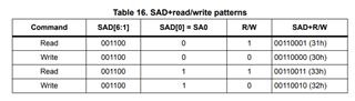
#define ACC_ADDR (0x33U >> 1)
#define X_OUT_L 0x28
#define SCL_PIN 5
#define SDA_PIN 2
/* Indicates if operation on TWI has ended. */
static volatile bool m_xfer_done = false;
/* TWI instance. */
static const nrf_drv_twi_t m_twi = NRF_DRV_TWI_INSTANCE(TWI_INSTANCE_ID);
/* Buffer for samples read from temperature sensor. */
static uint8_t m_sample;
/**
* @brief Function for setting active mode on MMA7660 accelerometer.
*/
void ACC_set_mode(void) {
ret_code_t err_code;
// set data rate to 100 Hz
uint8_t CTRL_REG1[] = {0x20, 0x5F};
// set full-scale to +/- 2g
uint8_t CTRL_REG4[] = {0x23, 0x80};
// set FIFO to stream mode
uint8_t FIFO_CTRL[] = {0x2E, 0x80};
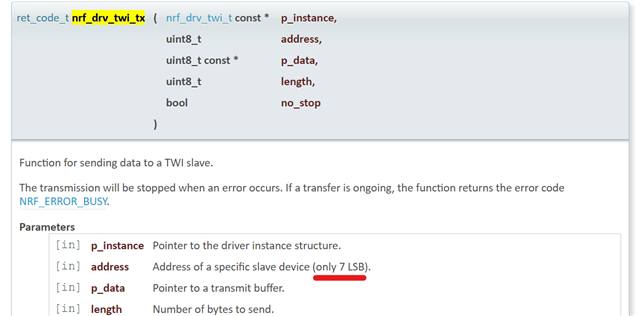
err_code = nrf_drv_twi_tx(&m_twi, ACC_ADDR, CTRL_REG1, sizeof(CTRL_REG1), false);
APP_ERROR_CHECK(err_code);
while (m_xfer_done == false);
m_xfer_done = false;
err_code = nrf_drv_twi_tx(&m_twi, ACC_ADDR, CTRL_REG4, sizeof(CTRL_REG4), false);
APP_ERROR_CHECK(err_code);
while (m_xfer_done == false);
m_xfer_done = false;
err_code = nrf_drv_twi_tx(&m_twi, ACC_ADDR, FIFO_CTRL, sizeof(FIFO_CTRL), false);
APP_ERROR_CHECK(err_code);
while (m_xfer_done == false);
}
/**
* @brief Function for handling data from temperature sensor.
*
* @param[in] temp Temperature in Celsius degrees read from sensor.
*/
__STATIC_INLINE void data_handler(uint8_t temp) {
printf("data: %d\n", temp);
}
/**
* @brief TWI events handler.
*/
void twi_handler(nrf_drv_twi_evt_t const *p_event, void *p_context) {
switch (p_event->type) {
case NRF_DRV_TWI_EVT_DONE:
if (p_event->xfer_desc.type == NRF_DRV_TWI_XFER_RX) {
data_handler(m_sample);
}
m_xfer_done = true;
break;
default:
break;
}
}
/**
* @brief UART initialization.
*/
void twi_init(void) {
ret_code_t err_code;
const nrf_drv_twi_config_t twi_acc_config = {
.scl = SCL_PIN,
.sda = SDA_PIN,
.frequency = NRF_DRV_TWI_FREQ_100K,
.interrupt_priority = APP_IRQ_PRIORITY_HIGH,
.clear_bus_init = false};
err_code = nrf_drv_twi_init(&m_twi, &twi_acc_config, twi_handler, NULL);
APP_ERROR_CHECK(err_code);
nrf_drv_twi_enable(&m_twi);
}
/**
* @brief Function for reading data from temperature sensor.
*/
static void read_sensor_data() {
printf("READING......\n");
uint8_t addr8 = X_OUT_L;
m_xfer_done = false;
ret_code_t err_code = nrf_drv_twi_tx(&m_twi, ACC_ADDR, &addr8, 1, true);
APP_ERROR_CHECK(err_code);
while (m_xfer_done == false);
err_code = nrf_drv_twi_rx(&m_twi, ACC_ADDR, &m_sample, sizeof(m_sample));
APP_ERROR_CHECK(err_code);
if(m_sample != 0){
nrf_gpio_pin_toggle(LED_1);
printf("read: %d\n", m_sample);
}
}
/**
* @brief Function for main application entry.
*/
int main(void) {
APP_ERROR_CHECK(NRF_LOG_INIT(NULL));
NRF_LOG_DEFAULT_BACKENDS_INIT();
twi_init();
nrf_gpio_cfg_input(3, NRF_GPIO_PIN_PULLUP);
nrf_gpio_cfg_output(4);
nrf_gpio_pin_write(4, 1);
nrf_gpio_cfg_output(8);
nrf_gpio_pin_write(8, 1);
nrf_gpio_cfg_output(LED_1);
ACC_set_mode();
while (true) {
nrf_delay_ms(500);
do {
__WFE();
} while (m_xfer_done == false);
// to confirm everything is still working
nrf_gpio_pin_toggle(LED_1);
read_sensor_data();
}
}
/** @} */
Feel free to tell me if you need more information.
Any recommendation will be highly appreciated. Thank you very much!!