I built an application for the nrf51822 on top of SDK12.3, to which I added the buttonless DFU based on the "experimental_ble_app_buttonless_dfu" example.
As a boot loader I used the one from case 256032 that Vidar Berg kindly provided.
I then followed the instructions from the Getting started with Nordic's Secure DFU bootloader, a step by step guide to build the settings, private key, and the .zip udpate package.
The nrf51-dk comes with a NRF51xxx_xxAC_REV3, and my custom board has a NRF51xxx_xxAA_REV3 chip.
The final solution is comprised of five files (I am also including the addresses for each of the .hex files):
1. Softdevice: s130_nrf51_2.0.1_softdevice.hex
contains the MBR (0x0 - 0x7C0) and the soft device (0x1000 - 0x1AFE0)
2. my_app.hex (0x1B000 - 0x220C4)
3. bootloader.hex (0x35C000 - 0x3DAE0)
4. settings.hex (0x3FC00 - 3FC5C)
5. The DFU .zip file to be used for updating, after booting the device into update mode
When flashing files 1 through 4 to the nrf51-DK, all works well:
- my app works from the start
- requesting to go into DFU mode also works (have only tried to do it with the nordic Connect android app yet, but it boots into update mode, changes mac address, and I can then update a new .zip update package, which after updating also runs properly)
Now my problem:
- When I flash the same 4 files to the nrf51822 on my own PCB, nothing happens. I see de device neither in normal mode (advertising from my app), nor in update mode (advertising "TargDFU").
- But if I flash again, but remove the boot loader, my app works (I need to keep the settings file, otherwise my app tries to boot into DFU mode and ends up in a loop as the boot loader isn't there)
- If I flash only the boot loader, it works on the nrf51-DK, but on the nrf51822 on my PCB it fails. When in debug mode I get these messages on the Output Window in Segger Embedded Studio:
Downloading 'secure_dfu_ble_s130_pca10028.elf' to J-Link
Programming 23.8 KB of addresses 00035c00 -- 0003bb53
Programming 0.0 KB of addresses 0003bb54 -- 0003bb63
Programming 7.8 KB of .rodata addresses 0003bb64 -- 0003dac3
Programming 0.0 KB of addresses 0003dac4 -- 0003dadf
Programming 0.0 KB of .uicrBootStartAddress addresses 10001014 -- 10001017
J-Link: Flash download: Bank 0 @ 0x00000000: Skipped. Contents already match
Download successful
Stopped by vector catch
And then the debugger stops at address 0x6B0
I am certainly missing something, just don't know what. It is also intriguing that it works as expected with the DK, but not on my board.
Can this be cause by some configuration problem since the RAM size on the DK chip is 32K and the one on my board opnly has 16K?
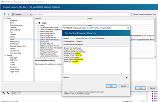
These are the settings I have on "linker_section_placement_macros":
FLASH_PH_START=0x0;
FLASH_PH_SIZE=0x40000;
RAM_PH_START=0x20000000;
RAM_PH_SIZE=0x8000;
FLASH_START=0x35C00;
FLASH_SIZE=0xA000;
RAM_START=0x20002C00;
RAM_SIZE=0x5380
RAM_PH_SIZE is set to 32K, which the DK has, but my xxAA_REV3 chip doesn't, so this one doesn't look correct.
Any ideas?
Best regards,
Ricardo