This post is older than 2 years and might not be relevant anymore
More Info: Consider searching for newer posts

SEGGER J-Link debugger/programmer for nRF52840

Hi,

I have developed some projects on nRF52840 DK pca10056.

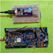
I want to program/debug the nRF52840 chip (this chip)  with SEGGER J-Link debugger/programmer (this debugger).

So I have the following questions.

1- Is this the right debugger I have selected? Or any other suggestion?
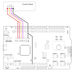
2- Is there any connection diagram(nRF52840 chip--with--SEGGER J-Link debugger/programmer)? I have not found it.
3- I need this setup to program many devices. So any suggestions?

Thanks! 

  • Hi Muqarrab,

    1- It should work.

    You can also use the nRF52840-DK instead. It has an on-board debugger that can also be used to flash and debug firmware on external SOCs.

    You just need to connect your external SOC through the debug out port. Once your external SOC is detected, the debugger will switch the connection to it, and ignore the on-board SOC.

    If you managed to have an SWD connector on your custom board, that'll be easier. You'll just need a cable to connect them both.

    Like in here. The custom board is the Adafruit nRF52840 Feather express.

    Or, you can just connect the SWD related pins on the P20 of the nRF52840-DK, to your custom board.

    Note: You do need to power your external board.

    2- You can just look for the SWD interface pins. That's all you need !

    3- You can still use the DK here too. But, if you have lot of devices, I think using an external debugger would be good, with some sort of pogo-pins, and a Tag-Connect footprint on the custom PCB.

    Find some tips about that here : https://partsbox.com/blog/choosing-a-debug-programming-connector-2019.html

    Hope that helps.

    Best regards,

  • Thank ,

    Do I need a level converter? As I have seen some chips have 3.3 operating voltage and some have 1.7-5.5v.


  • The target board must have the same VDD voltage as the DK. Otherwise you will need a level shifter. The standalone J-links have one built-in.

  • Hello, I'd like to add to 's answer. This is for when you use P20 for programming and debugging an external device.

    1- Use P20 on the board and make the connections he provided,  (I will use DK term for the device that has a J-link which will be connected to the external device that will be programmed such as a dongle)(you don't need to power the device if it's a dongle).

    2- Build your application for proper device (nrf52840, 52840 dongle, 52833... etc.)

    3- go to location <your_workspace_path\your_application_folder\build\zephyr> where we'll need the zephyr.bin and zephyr.hex files.

    4- Open J-Flash Lite (I'm using V7.66a version). Choose device to be programmed > click OK > click three dots below the "Data File (bin / hex / ...)....." find the zephyr.bin path located in step 3. 

    5- Click Program Device

    6- Repeat step 4 for zephyr.hex

    7- Click Program Device

    8- it should work.

    You might ask," why do you program .bin and after that the .hex file, wouldn't the .hex just overwrite anyway?" Nope. Although sometimes just flashing the .hex file works, most of the time it did'nt for me and I don't know why. It was a coincidence that I've discovered this. But I'm guessing it's something to do with bootloader. .hex files don't start form address 0x0, but I've discovered that .bin files do. So overwriting them somehow makes it work. Hope it helps. Any technical explanation on why this works is appreciated.  

  • Hello,

    The problem is that J-Flash Lite sometimes fail to reset the target after loading the FW binary. I reproduced it here, but not sure what the root cause is - maybe it's trying to do a pinreset before it is enabled.. Anyway. for development I suggest you use nrfjprog/west, or the Programmer app in nRF connect for desktop if you want a GUI alternative.

    IoTMAN said:
    but I've discovered that .bin files do

    zephyr.bin and zephyr.hex are linked to the same address. The difference with *.bin files is that they don't contain any address information, so you have to tell the programmer where to load the data (0x0 in this case). For multi-image builds (e.g. application + bootloader), you can use the merged.hex file instead (see https://developer.nordicsemi.com/nRF_Connect_SDK/doc/latest/nrf/ug_multi_image.html#what-are-image-files for a description of the different hex files that may be produced by the build process).

Related