This post is older than 2 years and might not be relevant anymore
More Info: Consider searching for newer posts

Toggle 2 LEDs back and forth with PPI, GPIOTE and timer

Hello,

I am using NRF52840 DK to toggle led 3 and 4 back and forth (when LED 3 is ON, LED 4 should be OFF and so on). I have to toggle them in a small time interval of 10ms. I am using SDK 17.02. In order for the power consumption I am using GPIOTE with PPI and timer. Right now I am using a single timer to drive both the LEDs. 

void timer_dummy_handler(nrf_timer_event_t event_type, void * p_context){}


static void led_blinking_setup()
{
    uint32_t compare_evt_addr_RED;
    uint32_t gpiote_task_addr_RED;
    uint32_t compare_evt_addr_IR;
    uint32_t gpiote_task_addr_IR;

    ret_code_t err_code;

    nrf_ppi_channel_t ppi_channel_RED;
    nrf_ppi_channel_t ppi_channel_IR;

    uint32_t ticks_RED = nrfx_timer_ms_to_ticks(&timer_gpio, 10); //same ticks for both IR and RED
    NRF_LOG_INFO("GPIO STARTED");


 nrf_drv_gpiote_out_clear(GPIO_OUTPUT_PIN_NUMBER1);

    nrf_drv_gpiote_out_config_t config = GPIOTE_CONFIG_OUT_TASK_TOGGLE(false);
    
    nrf_drv_gpiote_out_config_t config1=
    {
    .action  = NRF_GPIOTE_POLARITY_TOGGLE,                                               \
        .init_state =  NRF_GPIOTE_INITIAL_VALUE_HIGH , \
        .task_pin   = true 

   };
   
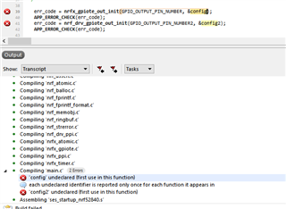
    err_code = nrf_drv_gpiote_out_init(GPIO_OUTPUT_PIN_NUMBER, &config);
    APP_ERROR_CHECK(err_code);

    err_code = nrf_drv_gpiote_out_init(GPIO_OUTPUT_PIN_NUMBER1, &config1);


    nrf_drv_timer_extended_compare(&timer_gpio, NRF_TIMER_CC_CHANNEL0, ticks_RED, NRF_TIMER_SHORT_COMPARE0_CLEAR_MASK, false);


    err_code = nrf_drv_ppi_channel_alloc(&ppi_channel_RED);
    APP_ERROR_CHECK(err_code);

   err_code = nrf_drv_ppi_channel_alloc(&ppi_channel_IR);
    APP_ERROR_CHECK(err_code);


    compare_evt_addr_RED = nrf_drv_timer_event_address_get(&timer_gpio, NRF_TIMER_EVENT_COMPARE0);
    gpiote_task_addr_RED = nrf_drv_gpiote_out_task_addr_get(GPIO_OUTPUT_PIN_NUMBER);


    compare_evt_addr_IR = nrf_drv_timer_event_address_get(&timer_gpio, NRF_TIMER_EVENT_COMPARE0);
    gpiote_task_addr_IR = nrf_drv_gpiote_out_task_addr_get(GPIO_OUTPUT_PIN_NUMBER1);


    err_code = nrf_drv_ppi_channel_assign(ppi_channel_RED, compare_evt_addr_RED, gpiote_task_addr_RED);
    APP_ERROR_CHECK(err_code);
    err_code = nrf_drv_ppi_channel_assign(ppi_channel_IR, compare_evt_addr_IR, gpiote_task_addr_IR);
    APP_ERROR_CHECK(err_code);


    err_code = nrf_drv_ppi_channel_enable(ppi_channel_RED);
    APP_ERROR_CHECK(err_code);
      err_code = nrf_drv_ppi_channel_enable(ppi_channel_IR);
    APP_ERROR_CHECK(err_code);


    nrf_drv_gpiote_out_task_enable(GPIO_OUTPUT_PIN_NUMBER);
   nrf_drv_gpiote_out_task_enable(GPIO_OUTPUT_PIN_NUMBER1);
}

The code works perfectly fine. But I believe there is a better way approach rather than this method. By using this method, one of the LED remains ON even after the required time of the activity ends. I need the signal to be precise and accurate and should not course any problem in the timing. They have to be synchronized perfectly. Is there any other better approach to this problem?

Would appreciate your help. Thank you. 

Parents
  • Hello,

    If the two LEDs are always the opposite of one another, I would try to make the two use the same timer for both gpios. 

    E.g. see if you can set the timer to run for 20ms, but set one compare at 10ms and one at 20ms. Remember to only NRF_TIMER_SHORT_COMPARE0_CLEAR_MASK at the 20ms compare.

    Then you have to set the ppi channels to turn one LED on and one off at 10ms, and vice versa at 20ms. In theory you should be able to use toggle with opposite starting conditions, but it is safer to set and clear the pins.

    Let me know if this was very unclear. I don't have a project that is set up the same as you, so if you get stuck, please try to upload the project folder (zip it and upload it here). 

    Best regards,

    Edvin

  • Hai Edvin,

    If I have understood you right, the below-given code would do the trick right? But I have trouble setting up and clearing the pins. So I have left that line empty. Is my approach correct? If so how can u add up the missing line? 

    static void led_blinking_setup()
    {
        uint32_t compare_evt_addr;
        uint32_t gpiote_task_addr;
        uint32_t compare_evt_addr1;
        uint32_t gpiote_task_addr1;
       
        nrf_ppi_channel_t ppi_channel;
        ret_code_t err_code;
    
       // Here comes the LED SET and CLEAR function
    
        uint32_t ticks_RED = nrfx_timer_ms_to_ticks(&timer, 20);
    
        nrf_drv_timer_compare(&timer, NRF_TIMER_CC_CHANNEL0, (ticks_RED/2), false);
        nrf_drv_timer_extended_compare(&timer, NRF_TIMER_CC_CHANNEL1, ticks_RED, NRF_TIMER_SHORT_COMPARE0_CLEAR_MASK, false);
    
        err_code = nrf_drv_ppi_channel_alloc(&ppi_channel);
        APP_ERROR_CHECK(err_code);
    
        compare_evt_addr = nrf_drv_timer_event_address_get(&timer, NRF_TIMER_EVENT_COMPARE0);
        gpiote_task_addr = nrf_drv_gpiote_out_task_addr_get(GPIO_OUTPUT_PIN_NUMBER);
    
        compare_evt_addr1 = nrf_drv_timer_event_address_get(&timer, NRF_TIMER_EVENT_COMPARE1);
        gpiote_task_addr1 = nrf_drv_gpiote_out_task_addr_get(GPIO_OUTPUT_PIN_NUMBER2);


        err_code = nrf_drv_ppi_channel_assign(ppi_channel, compare_evt_addr, gpiote_task_addr);
        APP_ERROR_CHECK(err_code);
        err_code = nrf_drv_ppi_channel_assign(ppi_channel, compare_evt_addr1, gpiote_task_addr1);
        APP_ERROR_CHECK(err_code);
        
        err_code = nrf_drv_ppi_channel_enable(ppi_channel);
        APP_ERROR_CHECK(err_code);
    
        nrf_drv_gpiote_out_task_enable(GPIO_OUTPUT_PIN_NUMBER);
        nrf_drv_gpiote_out_task_enable(GPIO_OUTPUT_PIN_NUMBER2);
    }
    

    regards,

    Adarsh

  • Hai Edvin,

    Sorry for the missleadings.

    As Daniel mensioned I was able to work my application with single ppi channel using fork functionality. The file is  gpiote- Daniel.zip here.

    But as you mentioned, there is a risk of one LED to remain in the false state at some time during the application when driven by higher priority interrupt.

    So as you suggested, I initialized two PPI channel. Then I set the timer to run at 20ms and set one compare at 10ms and the other at 20ms. Now I am having difficulties in assigning the tasks to set and clear the pins. Here I am uploading the whole file. Kindly have a look.

    gpiote- Edvin.zip 

    Thank you

    Regards,

    Adarsh

  • I can't compile the project. Where do you declare/define config and config2?

    Please try to unzip the project in an unmodified SDK before you upload it. It is a simple way to check that you didn't do any changes outside the project folder.

    BR,

    Edvin

  • Hi Edvin,

    Sorry for the delay. Can you check into the code and see what is missing. I think I am not properly assigning the address to PPI channel. 

    gpiote.zip

    kind regards,

    Adarsh

  • Hello,

    First of all you should be careful when you call APP_ERROR_CHECK(err_code) on an err_code that has not received a value, like you do in led_blinking_setup(), right after the lines:

    nrf_ppi_channel_t ppi_channel;

    and

    nrf_ppi_channel_t ppi_channel1;

    I am not sure exactly what you have been trying to do. Did you intend to use:

    nrf_drv_gpiote_out_config_t config1 = GPIOTE_CONFIG_OUT_TASK_HIGH;
    nrf_drv_gpiote_out_config_t config2 = GPIOTE_CONFIG_OUT_TASK_LOW;

    Remember that one of them will set the pin low, and the other will set the pin high. 

    another thing:

    nrf_drv_timer_compare(&timer, NRF_TIMER_CC_CHANNEL0, (ticks_RED/2), true);
    nrf_drv_timer_extended_compare(&timer, NRF_TIMER_CC_CHANNEL1, ticks_RED, NRF_TIMER_SHORT_COMPARE0_CLEAR_MASK, true);

    You set CC0 shorter than CC1, and you reset the timer on CC0 (Compare0_clear_mask). Change it to NRF_TIMER_SHORT_COMPARE1_CLEAR_MASK, if you want the timer to count to reach CC1 = ticks_RED.

    Check out these two modified implementations:

    using 2 PPI channels:

    static void led_blinking_setup()
    {
        uint32_t compare_evt_addr;
        uint32_t gpiote_task_addr;
        uint32_t compare_evt_addr1;
        uint32_t gpiote_task_addr1;
        uint32_t err_code;
       
        nrf_ppi_channel_t ppi_channel;
        //APP_ERROR_CHECK(err_code);
    
        nrf_ppi_channel_t ppi_channel1;
        //APP_ERROR_CHECK(err_code);
    
        nrf_drv_gpiote_out_config_t config1 = GPIOTE_CONFIG_OUT_TASK_TOGGLE(true);
        nrf_drv_gpiote_out_config_t config2 = GPIOTE_CONFIG_OUT_TASK_TOGGLE(true);
        //nrf_drv_gpiote_out_config_t config1 = GPIOTE_CONFIG_OUT_TASK_HIGH;
        //nrf_drv_gpiote_out_config_t config2 = GPIOTE_CONFIG_OUT_TASK_LOW;
    
       err_code = nrfx_gpiote_out_init(GPIO_OUTPUT_PIN_NUMBER, &config1);
        APP_ERROR_CHECK(err_code);
        err_code = nrf_drv_gpiote_out_init(GPIO_OUTPUT_PIN_NUMBER2, &config2);
        APP_ERROR_CHECK(err_code);
    
        uint32_t ticks_RED = nrfx_timer_ms_to_ticks(&timer, 200);
    
        nrf_drv_timer_compare(&timer, NRF_TIMER_CC_CHANNEL0, (ticks_RED/2), true);
        nrf_drv_timer_extended_compare(&timer, NRF_TIMER_CC_CHANNEL1, ticks_RED, NRF_TIMER_SHORT_COMPARE1_CLEAR_MASK, true);
    
        err_code = nrf_drv_ppi_channel_alloc(&ppi_channel);
        APP_ERROR_CHECK(err_code);
        err_code = nrf_drv_ppi_channel_alloc(&ppi_channel1);
        APP_ERROR_CHECK(err_code);
     
        compare_evt_addr = nrf_drv_timer_event_address_get(&timer, NRF_TIMER_EVENT_COMPARE0);
        gpiote_task_addr = nrf_drv_gpiote_out_task_addr_get(GPIO_OUTPUT_PIN_NUMBER);
    
        compare_evt_addr1 = nrf_drv_timer_event_address_get(&timer, NRF_TIMER_EVENT_COMPARE1);
        gpiote_task_addr1 = nrf_drv_gpiote_out_task_addr_get(GPIO_OUTPUT_PIN_NUMBER2);
    
    
        err_code = nrf_drv_ppi_channel_assign(ppi_channel, compare_evt_addr,gpiote_task_addr);
        APP_ERROR_CHECK(err_code);
        err_code = nrf_drv_ppi_channel_assign(ppi_channel1, compare_evt_addr1, gpiote_task_addr1);
        APP_ERROR_CHECK(err_code);
        
        err_code = nrf_drv_ppi_channel_enable(ppi_channel);
        APP_ERROR_CHECK(err_code);
        err_code = nrf_drv_ppi_channel_enable(ppi_channel1);
        APP_ERROR_CHECK(err_code);
    
        nrf_drv_gpiote_out_task_enable(GPIO_OUTPUT_PIN_NUMBER);
        nrf_drv_gpiote_out_task_enable(GPIO_OUTPUT_PIN_NUMBER2);
    }

    Using 1 PPI channel:

    static void led_blinking_setup2()
    {
        uint32_t compare_evt_addr;
        uint32_t gpiote_task_addr;
        uint32_t compare_evt_addr1;
        uint32_t gpiote_task_addr1;
        uint32_t err_code;
       
        nrf_ppi_channel_t ppi_channel;
        //APP_ERROR_CHECK(err_code);
    
        //nrf_ppi_channel_t ppi_channel1;
        //APP_ERROR_CHECK(err_code);
    
        nrf_drv_gpiote_out_config_t config1 = GPIOTE_CONFIG_OUT_TASK_TOGGLE(true);
        nrf_drv_gpiote_out_config_t config2 = GPIOTE_CONFIG_OUT_TASK_TOGGLE(false); //false reverses the starting state.
        //nrf_drv_gpiote_out_config_t config1 = GPIOTE_CONFIG_OUT_TASK_HIGH;
        //nrf_drv_gpiote_out_config_t config2 = GPIOTE_CONFIG_OUT_TASK_LOW;
    
       err_code = nrfx_gpiote_out_init(GPIO_OUTPUT_PIN_NUMBER, &config1);
        APP_ERROR_CHECK(err_code);
        err_code = nrf_drv_gpiote_out_init(GPIO_OUTPUT_PIN_NUMBER2, &config2);
        APP_ERROR_CHECK(err_code);
    
        uint32_t ticks_RED = nrfx_timer_ms_to_ticks(&timer, 200);
    
        //nrf_drv_timer_compare(&timer, NRF_TIMER_CC_CHANNEL0, (ticks_RED/2), true);
        //nrf_drv_timer_extended_compare(&timer, NRF_TIMER_CC_CHANNEL1, ticks_RED, NRF_TIMER_SHORT_COMPARE1_CLEAR_MASK, true);
        nrf_drv_timer_extended_compare(&timer, NRF_TIMER_CC_CHANNEL0, ticks_RED, NRF_TIMER_SHORT_COMPARE0_CLEAR_MASK, true);
    
        err_code = nrf_drv_ppi_channel_alloc(&ppi_channel);
        APP_ERROR_CHECK(err_code);
        //err_code = nrf_drv_ppi_channel_alloc(&ppi_channel1);
        //APP_ERROR_CHECK(err_code);
     
        compare_evt_addr = nrf_drv_timer_event_address_get(&timer, NRF_TIMER_EVENT_COMPARE0);
        gpiote_task_addr = nrf_drv_gpiote_out_task_addr_get(GPIO_OUTPUT_PIN_NUMBER);
    
        //compare_evt_addr1 = nrf_drv_timer_event_address_get(&timer, NRF_TIMER_EVENT_COMPARE1);
        gpiote_task_addr1 = nrf_drv_gpiote_out_task_addr_get(GPIO_OUTPUT_PIN_NUMBER2);
    
    
        err_code = nrf_drv_ppi_channel_assign(ppi_channel, compare_evt_addr,gpiote_task_addr);
        APP_ERROR_CHECK(err_code);
        err_code = nrf_drv_ppi_channel_fork_assign(ppi_channel, gpiote_task_addr1);
        APP_ERROR_CHECK(err_code);
        
        err_code = nrf_drv_ppi_channel_enable(ppi_channel);
        APP_ERROR_CHECK(err_code);
    
        nrf_drv_gpiote_out_task_enable(GPIO_OUTPUT_PIN_NUMBER);
        nrf_drv_gpiote_out_task_enable(GPIO_OUTPUT_PIN_NUMBER2);
    }

    I mentioned using different tasks for setting and clearing the pins. That is a bit difficult using this implementation, because you fetch the address of the task by referencing the pin, but it is possible to set up several tasks per pin. One way is to do the following:

    // This function sets up TIMER3, the PPI and the GPIOTE modules to configure a single PWM channel
    // Timer CC num, PPI channel nums and GPIOTE channel num is defined at the top of this file
    void pwm0_init(uint32_t pinselect)
    {  
        NRF_GPIOTE->CONFIG[PWM0_GPIOTE_CH] = GPIOTE_CONFIG_MODE_Task << GPIOTE_CONFIG_MODE_Pos | 
                                             GPIOTE_CONFIG_POLARITY_Toggle << GPIOTE_CONFIG_POLARITY_Pos | 
                                             pinselect << GPIOTE_CONFIG_PSEL_Pos | 
                                             GPIOTE_CONFIG_OUTINIT_High << GPIOTE_CONFIG_OUTINIT_Pos;
    
        NRF_PPI->CH[PWM0_PPI_CH_A].EEP = (uint32_t)&NRF_TIMER3->EVENTS_COMPARE[PWM0_TIMER_CC_NUM];
        NRF_PPI->CH[PWM0_PPI_CH_A].TEP = (uint32_t)&NRF_GPIOTE->TASKS_CLR[PWM0_GPIOTE_CH];
        NRF_PPI->CH[PWM0_PPI_CH_B].EEP = (uint32_t)&NRF_TIMER3->EVENTS_COMPARE[TIMER_RELOAD_CC_NUM];
        NRF_PPI->CH[PWM0_PPI_CH_B].TEP = (uint32_t)&NRF_GPIOTE->TASKS_SET[PWM0_GPIOTE_CH];
        
        NRF_PPI->CHENSET               = (1 << PWM0_PPI_CH_A) | (1 << PWM0_PPI_CH_B);
    }

  • Hi,

    Thank you for that detailed discription. Yes I was trying to use different task for setting and clearing pins. 

    regards,

    Adarsh

Reply Children
No Data
Related