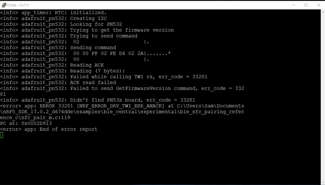
I have the Adafruit PN532 Shield v1.3 mounted to an nRF52840 DK, trying to run the ble_nfc_pairing_reference_c example from SDK 17. With no modification to the example code, I was getting the following output.
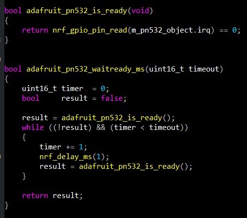
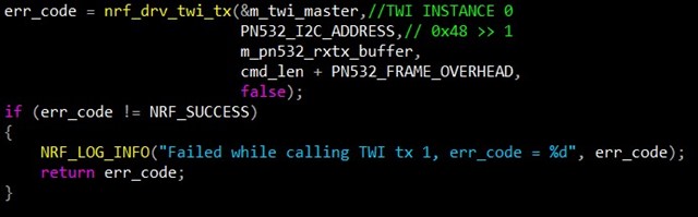
After some debugging I found the error was returning from the nrf_drv_twi_tx function with these default arguments passed.
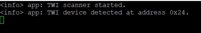
To investigate, I flashed the twi_scanner example and successfully found the PN532 at address 0x24.
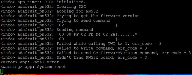
Since this doesn't match the PN532_I2C_ADDRESS being passed in the nfc reference example, I changed (0x48 >> 1) to (0x24). This resulted in the following output.
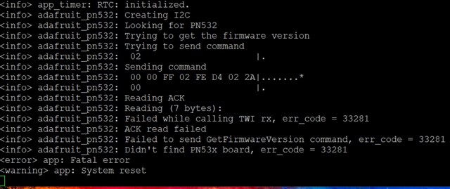
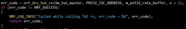
The only difference being that the tx function seemed to send data successfully, but the nrf_drv_twi_rx function that passes those same parameters was returning a wild error while trying to read the acknowledgement.
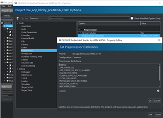
Since I was getting two different error scenarios, I re-extracted a fresh SDK 17 and tried again, but the exact behavior occurred. Does anyone know what is going on here?
My theory is that either there is something wrong with the Adafruit hardware, or these parameters are not configured correctly, unless I'm missing something.
Any help here would be much appreciated.
Thanks in advance!
Sam